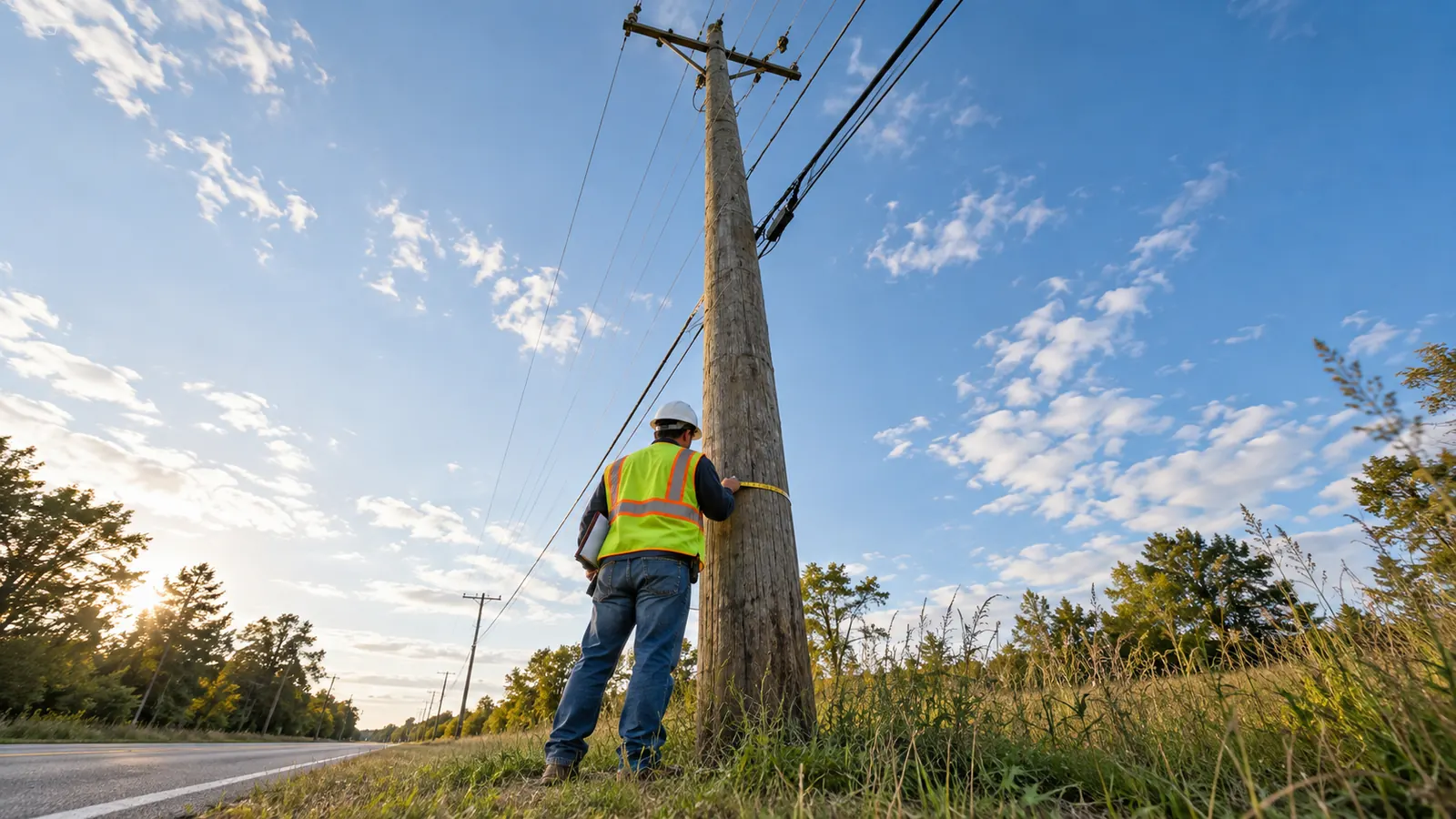
What utility poles carry
Utility poles are vertical structures that support overhead electric distribution conductors and communications cables. Wood distribution poles commonly run 35 to 50 feet long, according to Mississippi State University Extension Publication 1777. Installed height is lower because part of the pole is buried; attachment capacity requires a separate engineering review.
A line of poles can make an aerial fiber route look settled before anyone has checked it. Although the supports already exist, the available space changes from pole to pole, and the cable must maintain required clearances throughout each span, including where the ground rises beneath it.
We start with the function of the structure. A telephone pole may carry communications alone, while a power distribution pole can support electric facilities and communications attachments under a joint-use arrangement. We still have to establish ownership and obtain permission for an ISP to attach, whichever everyday name people use for the structure.
A short guide to the attachment spaces
Electric supply facilities generally occupy the upper portion of a joint-use distribution pole, with communications below the required separation space. Transformers and service drops can complicate that arrangement. Our guide to the parts of a utility pole explains the components in more detail; here, the key question is whether the proposed cable fits the complete installation.
From the pole face, a cable may appear comfortably above a driveway even though it sags into a clearance conflict farther out in the span. We need the span profile before selecting the attachment height, especially when a crossing or a change in grade controls the design.
Who owns utility poles and who may share them?
Pole owners include investor-owned utilities, electric cooperatives, municipal utilities and telecommunications companies. An investor-owned utility is a privately owned utility business; a cooperative serves its member owners; a municipal utility belongs to a local government. A telecom owner may own a communications-only line or share structures with an electric utility.
Joint use separates the pole from its attachments
The company that owns a pole may differ from every company whose cable hangs on it, leaving several parties responsible for the facilities on one structure. We establish the asset owner using its records and field identification, then identify the parties responsible for existing attachments. A familiar cable logo can help us identify the cable owner, but we need the pole records to establish who owns the supporting structure.
Confirm the owner first. A route that crosses an ownership boundary can require a different application package, even when the poles and attachment heights look unchanged from the road. We carry that boundary into the route inventory so the engineering package goes to the party authorized to review it.
Joint-use and attachment agreements govern access and responsibilities. Federal coverage also varies by owner: 47 U.S.C. 224 excludes cooperatively organized and government-owned entities from its definition of a covered utility, and its state-regulation provisions affect jurisdiction. We confirm the applicable process instead of assuming an investor-owned utility's attachment procedure applies to a co-op or municipality.
Pole access and land rights
A pole license covers the structure. The underlying easement or right-of-way can raise a separate question about the proposed communications route, particularly where existing facilities cross private land. We ask who holds the relevant rights and what those rights permit before a replacement or new guy location becomes part of the design.
Owner records also help resolve paired poles. One may be a replacement awaiting transfers, while the older structure still carries active attachments. During the survey, we identify which pole is intended to remain and ask the owner how the transfer work affects the new attachment application.
Keep an unresolved-owner flag. When a pole tag and the owner's map disagree, retain both observations in the survey record and request confirmation before assigning the application. Guessing here can send an otherwise usable package to the wrong reviewer.
What utility poles are made of
Wood, steel, concrete and fiberglass composite poles require different inspection and attachment details. We choose a replacement around the owner's approved standards and the site's loads, rather than treating every material with the same nominal height as interchangeable. The comparison below identifies the design question each material brings to a distribution route.
| Material | Structural characteristic | Attachment design focus |
|---|---|---|
| Preservative-treated wood | Natural tapered member with species-dependent properties | Verified class and condition; approved holes and hardware |
| Steel | Engineered tubular member | Specified connection details and corrosion protection |
| Concrete | Reinforced or prestressed member | Approved attachment positions and lifting provisions |
| Fiberglass composite | Fiber-reinforced polymer member | Product-specific drilling and connection requirements |
Wood: useful only with a verified condition
Wood poles use selected tree stems. Southern pine is one common pole species; Douglas-fir and western red cedar are also used. The North American Wood Pole Coalition's How Poles Are Made describes how selection for suitable size and form begins the production process. Selection and grading give the finished pole its standing as a structural product, beyond the preparation involved in stripping the log.
Decay can reduce the usable section of an installed wood pole. To determine how much sound wood remains at a critical location, we use the owner's accepted inspection information alongside the visible condition of the structure. If a brand is unreadable or a condition finding remains unresolved, we carry the question back to the owner before entering that information in the model.
Steel: check the connection detail
Steel poles use an engineered section whose capacity depends on its geometry and material properties. For an attachment application, we request the pole's structural data and approved connection method. Before locating holes in the shaft, we check that the detail suits the steel section, since transferring a wood-pole drilling detail could change the structural result.
Concrete: plan attachments and handling together
Concrete poles may be reinforced or prestressed, so drilling can affect embedded structural components. We establish permitted attachment locations first. Replacement planning also needs access for handling the specified pole, particularly where the existing line is reachable only through a narrow corridor and the installation equipment must work around energized facilities.
Fiberglass: use the specified composite system
Fiberglass poles are fiber-reinforced polymer structures. Because fiberglass poles have no universal class, we need the particular system's wall construction and connection requirements to specify an attachment. A proposed substitution also needs approved drilling and hardware details so we can evaluate how the assembled pole and its connections will perform under the design loads.
How wood poles are produced and treated
Production begins with selecting a stem that meets the required dimensions and quality criteria. Peeling removes bark; seasoning or conditioning prepares the wood for treatment. Preparation can include incising to help preservative penetration; the species and treatment process determine whether this step is needed. The North American Wood Pole Coalition describes pressure treatment as the step that drives preservative into the wood.
For treatment documentation, we refer to the USDA Forest Products Laboratory's Wood Handbook: Wood as an Engineering Material, FPL-GTR-282, published in 2021, chapter on wood preservation, distinguishes preservative penetration from retention: how far treatment enters the wood and how much remains. Procurement should request documentation covering both measures in the treatment specification, and field cuts or drilled holes need the owner's specified protection.
Our preference for reusing a serviceable wood pole has a limitation: reliable loading calculations still depend on condition information that a routine attachment photograph cannot supply. Additional inspection can therefore be necessary before we recommend retention. A new cable request is a useful point to resolve that uncertainty, before construction depends on the pole staying in service.
How tall are utility poles, and how far apart are they?
Pole length and installed height answer different questions. Mississippi State University Extension's 35 to 50 foot range describes distribution pole length, including the buried portion. We keep that distinction in the survey record because substituting nominal length for measured height overstates the space available for attachments and can hide a clearance problem.
Length, class and setting depth
Consider an illustrative 40-foot pole with 6 feet below the ground line: 34 feet remain above ground, before accounting for lean or changes in grade. To select the setting depth for an actual installation, we also need soil resistance and the pole's applied loads to support the detail accepted by the owner. The subtraction simply explains the relationship between total length and exposed height.
Class describes a strength category. ANSI O5.1-2022, Wood Poles: Specifications and Dimensions, relates wood pole dimensions and quality requirements to species and class; a class mark does not report today's remaining capacity. Our ANSI O5.1 pole specifications guide covers that distinction without turning a field brand into permission for another attachment.
For a reference lookup, our free Utility Pole Charts provide minimum wood pole circumference, diameter, setting depth and class load by species, class and length, from USDA RUS Bulletin 1724E-150 (ANSI O5.1 minimums). That bulletin, Unguyed Distribution Poles: Strength Requirements, was issued August 14, 2014. Use the reference alongside the owner's requirements. Our utility pole depth chart guide explains the setting-depth assumptions that require further review.
Typical spacing is a planning reference
There is no single standard span for every distribution route. As a bounded example, the Bureau of Reclamation's December 2015 Helena Valley Irrigation District Lease of Power Privilege Final Environmental Assessment described typical spacing of 200 to 250 feet for the proposed distribution line, while explicitly noting that terrain could change it. Terrain that shortens the usable span would require closer spacing, so we use that range as context for the cited proposal rather than as a nationwide design limit.
As spans get longer, cable sag and tension change; a road crossing can require a different attachment elevation from an adjacent field span. At a line angle, the cable pull also changes direction. We evaluate the affected structures together because moving one attachment can change the loads and clearances at its neighbors.
Measure the controlling crossing. If a driveway crest or raised road surface sits under a span, capture its elevation in the survey. An attachment-height measurement taken only at each pole can miss the ground point that governs the cable clearance.
Extra pole height may solve a clearance conflict while increasing the bending effect of a given horizontal load applied higher on the structure. A shorter span may reduce sag but require another pole location and permission to occupy it. We compare those options before committing the route to a replacement schedule.
How a new attachment reaches an engineered make-ready plan
Attachment engineering begins with the proposed cable and the owner's design criteria. We need the construction method at this stage because self-supporting and strand-supported cables create different inputs in the loading model. That choice determines how we represent the proposed work in the analysis. Substituting either after approval requires a review of the affected calculations and drawings.
Build the model from the field record
For each pole, we bring together photographs, measured span geometry and existing attachment heights so the analysis reflects the field record. Cable properties need an accepted basis as well. Where facilities remain unknown, we keep the inputs unresolved until the owner or attacher supplies that information; a neatly completed model would otherwise conceal the uncertainty.
Check the complete load path. The pole carries forces from the conductors and attached equipment into its support, with guys and anchors participating where present. Our analysis must represent the actual arrangement under the required loading cases. Adding a guy on paper is useful only when its location and anchor installation are feasible.
The 2023 National Electrical Safety Code, IEEE C2-2023, published in August 2022, addresses overhead supply and communications lines. We establish the edition and amendments applicable to the project, together with owner requirements, before selecting loading cases or clearance criteria, and each clearance value must retain its voltage and crossing conditions. Copying an isolated number between unlike installations loses the rule's meaning.
Turn the result into work that can be built
Make-ready is the work required to prepare an existing pole line for the proposed attachment. It can involve moving facilities or replacing a pole when the accepted design cannot retain the existing structure. Each move needs an assigned responsible party so the design note reaches someone who can arrange the work as the fiber construction schedule advances.
Our pole loading analysis for new attachments connects the surveyed structure to that decision. Draftech's engineering is 100% in-house. We carry the proposed attachment through the calculations and make-ready drawings, with the same pole identifiers in the application so the owner can trace a requested change back to its supporting record.
During a replacement, electric facilities may need to be transferred before communications attachments can move, and the old pole may remain until the final transfer is complete. We ask the owner to identify release conditions explicitly. Full turnkey construction is delivered by Draftech-managed subcontract crews under Draftech's QA/QC and safety program.
Recommended next steps for pole owners and attachers
Utilities and co-ops: Establish the pole inventory and condition basis before offering attachment capacity. We recommend resolving missing structural data early, then issuing the accepted loading criteria so every applicant evaluates the same asset on a consistent basis. Keep replacement and transfer responsibilities visible in the approval record.
ISPs and carriers: Define the proposed cable before commissioning the attachment survey. In our route review, we compare aerial options against known ownership boundaries and crossing constraints to identify a route that can support an approvable application. Reserve cable substitutions for engineering review rather than allowing procurement changes to bypass the accepted design.
Municipalities: Separate the municipality's role as pole owner from its right-of-way authority. Our recommendation is to assign a reviewer for each responsibility and check whether a proposed replacement occupies land the current agreement covers. Naming the reviewing department gives applicants an identifiable decision path when several departments participate.
For owners planning work across jurisdictions, our service coverage is stated plainly: Active in 24 states. Available across all 50 U.S. states. The Draftech partner team provides the organizational point of contact; the pole owner's technical standards still govern the submitted design and acceptance process.
Before scheduling aerial construction, bring any missing pole data and unresolved transfer work into the attachment review. We can address those gaps through a coordinated attachment engineering package; send the route and the owner's submission requirements to info@draftech.com so we can define the work that needs to be resolved.
For a qualifying route, Draftech engineers the first 20,000 linear feet at no cost, from feasibility and field survey through permit approval, through our free-design offer. The owner reviews each request to establish whether the route fits the offer before Draftech commits the package and begins engineering work.