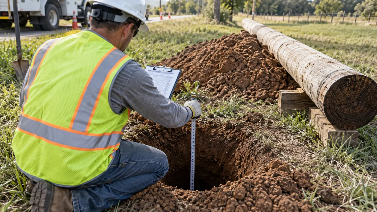
A deeper setting takes height away from the attachments above it. That tradeoff can disappear when a preliminary depth is copied into a pole schedule and the attachment drawing keeps its original elevations. We check the relationship before the pole is ordered, while the selection can still change without disrupting the construction package.
What a utility pole depth chart tells you
A utility pole depth chart relates total pole length to the portion set below ground. The common rule of thumb is 10 percent of pole length plus 2 feet: a 40-foot pole gives 6 feet. Soil, class and the pole owner's standards govern the actual setting depth.
A pole ordered as 40 feet includes the buried portion, so a 6-foot setting leaves 34 feet above the reference groundline in a simplified vertical installation. That subtraction establishes geometry before attachment selection. Measuring 40 feet above ground and calling it a 40-foot pole would put the wrong member into the model.
Establish the groundline before doing arithmetic
The reference groundline controls both embedment and exposed height. On a slope, the uphill and downhill surfaces give different measurements; a grading plan can also move the eventual groundline away from the surface recorded during fielding. Identify the depth reference on the drawing. Otherwise, the field record can appear to agree with the design while describing a different section of the pole.
For an existing structure, the visible height alone cannot establish the buried length unless the total length is reliably known. A readable brand and an installation record can help resolve the question, but each needs to be checked against the pole being surveyed. Uncertain embedment remains an assumption to resolve. Filling that field with a default makes the model look more certain than the evidence supports.
Keep the source's scope attached to its numbers
USDA Rural Utilities Service Bulletin 1724E-150, Unguyed Distribution Poles: Strength Requirements, issued August 14, 2014, addresses unguyed wood distribution poles up to 55 feet long. Its historical references include ANSI O5.1-2008, Specifications and Dimensions for Wood Poles. We treat those published tables as reference data and check the owner's adopted requirements before using them in a current design.
Published tables differ, even for equal lengths. For example, Table W in RUS Bulletin 1728F-803, Specifications and Drawings for 24.9/14.4 kV Line Construction, published December 15, 1998, lists 6 feet in soil for a 35-foot pole. The common rule-of-thumb calculation gives 5.5 feet. That difference is why we identify the applicable owner standard before assigning a construction depth.
Keep the depth label: Mark an early estimate as preliminary wherever it travels. A value copied from a feasibility worksheet into a construction schedule should retain its assumption until the responsible engineer resolves it against the owner's requirements.
Utility pole depth chart by length and class
The short chart below shows arithmetic examples for wood poles, with illustrative class labels to keep class separate from length. These are rule-of-thumb depths, not installation instructions. Soil, class and the pole owner's standards govern. We deliberately repeat the 40-foot length with different classes because changing class does not change this formula, even though it changes the structural selection and can affect the foundation design.
Read the class column as a sample designation, not a recommended purchase. A utility may require a different class or a deeper setting at any listed length. For class dimensions and strength terminology, use our ANSI O5.1 pole specifications guide. The table here stays focused on how total length becomes exposed height; it does not reproduce the species and circumference tables.
| Total pole length | Illustrative class | Rule-of-thumb depth | Calculated exposed height |
|---|---|---|---|
| 35 ft | Class 5 | 5.5 ft | 29.5 ft |
| 40 ft | Class 4 | 6.0 ft | 34.0 ft |
| 40 ft | Class 2 | 6.0 ft | 34.0 ft |
| 45 ft | Class 3 | 6.5 ft | 38.5 ft |
| 50 ft | Class 2 | 7.0 ft | 43.0 ft |
The 35-foot row needs an owner-table check
The first row is useful precisely because it exposes the limit of a formula. If the governing schedule calls for a 6-foot setting, the exposed height of that 35-foot pole becomes 29 feet, not 29.5 feet. We would carry 29 feet into the geometry for that case. The half-foot difference belongs in the attachment and clearance review before someone treats the original elevations as fixed.
Equal length does not mean equal structural capacity
The two 40-foot examples leave the same calculated exposed height, but the class labels identify different structural selections. We assess the specified species and dimensions with the loads rather than treating equal height as equal capacity. Stronger poles still need adequate foundations. Replacing the pole class in a software catalog does not establish that the surrounding soil can resist the revised reactions.
The 45-foot and 50-foot rows show another useful distinction: added total length is partly buried under the rule of thumb. Moving from 40 to 45 feet adds 4.5 feet of calculated exposed height, not 5 feet. Moving from 45 to 50 feet does the same. These examples describe geometry only. A deeper owner-required setting can reduce the usable gain further.
When checking dimensions beside the proposed pole schedule, our Utility Pole Charts provide free reference charts of minimum wood pole circumference, diameter, setting depth and class load by species, class and length, from USDA RUS Bulletin 1724E-150 using ANSI O5.1 minimums. We keep the selected source and its assumptions with the design record so a reference value remains distinguishable from the approved setting.
How soil changes the setting decision
The embedded pole transfers load into the surrounding ground. That ground has to supply resistance. A depth that is acceptable under an owner's standard detail for suitable soil may require a different treatment where the excavation exposes weak material, especially when the proposed pole carries a substantial lateral reaction or sits near an unstable edge.
Soft ground and disturbed backfill need a design response
We flag questionable soil during planning so the foundation question reaches the responsible engineer before the pole order is fixed. Standing water or an excavation through uncontrolled fill gives the designer a reason to investigate; neither observation supplies a soil strength by itself. The response may require geotechnical input and an owner-approved foundation detail. Choosing an arbitrary extra foot of burial would leave the underlying capacity question unanswered.
Standard details have a limitation. Our preference for them can encourage a desk review to accept a familiar setting without asking whether the site matches the detail's assumptions. We address that by recording the conditions that would trigger a field referral. The drawing should tell the construction team who resolves an unexpected condition and what information that person needs before accepting a change.
Rock and slopes require their own interpretation
Rock refusal deserves attention to the actual material and hole geometry. Encountering a hard layer does not establish that the full embedment is in competent rock. We ask the designer to apply the owner's rock-setting detail to the observed conditions, including any soil cover, instead of shortening the specified setting solely because the auger stopped advancing. The resulting detail must remain consistent with the pole schedule.
Why setting depth matters to pole loading
Embedment sets the geometry above ground and contributes to the support below it. Both matter to the result. A loading analysis can check the wood member against calculated demand while still relying on an assumed foundation, so we identify what the model establishes and what requires a separate soil or embedment check before accepting the replacement.
Attachment elevations change the bending demand
For a simplified horizontal point load, moment about the groundline equals force multiplied by height. As an illustrative calculation, a 1,000-pound force applied 30 feet above ground produces 30,000 foot-pounds before any applicable load factors. At 32 feet, the same force produces 32,000 foot-pounds. These assumed numbers demonstrate the geometry. They do not represent a permissible load or a complete pole analysis.
The consequence depends on what moves. Setting the same pole deeper lowers its top, but an attachment may have to remain at its original elevation to satisfy clearance. In that case, reducing the modeled attachment height would give credit the design cannot use. We establish required attachment elevations independently. After assigning the final depth, we check whether the selected pole still accommodates them.
Our pole loading analysis for replacement decisions addresses the structural demand that sits behind that choice. We compare the proposed arrangement with the existing condition and identify the assumptions that affect the result. Where embedment remains uncertain, the report needs to say so explicitly rather than allowing a passing wood-stress result to imply that the foundation has also been verified.
Recheck after a depth change: Carry the revised groundline and attachment elevations back into the loading model. Updating only the construction note can leave the approved analysis describing a pole geometry that will never be installed.
A depth assumption can hide in otherwise good field data
A survey can locate attachments accurately while leaving the buried portion unresolved. We distinguish measured values from inferred ones in the pole record, then use the uncertainty to decide what needs verification. The utility pole loading field measurement guide covers the above-ground inputs that support this review. A photograph of the pole top cannot settle an embedment question at the butt.
Carry the depth into replacement design and closeout
A replacement schedule needs total length and setting depth to agree with the attachment drawing. We review that relationship before procurement. For example, a 45-foot pole at an illustrative 7.5-foot engineered setting leaves 37.5 feet exposed, a full foot less than the rule-of-thumb example in the chart. Whether the proposed arrangement fits must be checked against that revised geometry.
Show the approved detail and record what was installed
The issued drawing should identify the governing setting detail and any site-specific departure from it. We want a construction reviewer to find the depth beside the correct pole identifier, with the ground reference clear enough to reproduce. Where field conditions prevent the specified setting, the change needs engineering review before it becomes a revised installation instruction. An unexplained redline leaves the owner with an unresolved design assumption.
Closeout should preserve the installed depth and the approved disposition of any change. We connect that record to the replacement identifier so a future attachment review can retrieve it without guessing which retired pole the note described. Our electric utility as-built drawings guide explains how construction changes become usable asset records. The buried portion deserves the same record discipline as the visible attachments.
Choose the next step for your pole program
For pole owners: Issue the applicable setting standard with the replacement scope and define the referral process for unsuitable ground. Keep exceptions tied to individual pole identifiers. That makes the intended depth reviewable before construction and gives the acceptance team a specific approved detail to compare with the installed condition.
For attachment applicants: Resolve uncertain existing embedment with the owner before relying on a loading result to retain a pole. We recommend separating the measured geometry from the assumed foundation inputs in the submittal. If replacement is required, request the approved pole arrangement early enough to coordinate the proposed attachment elevation with the other occupants.
For construction managers: Treat a field depth change as a design referral. Do not recover lost above-ground space by reducing the setting on site. Send the observed obstruction and its location to the responsible engineer, then record the accepted revision against the installation. Update both drawing and closeout package.
Draftech International delivers turnkey telecom and power infrastructure with 100% in-house engineering and full turnkey construction through Draftech-managed subcontract crews. Active in 24 states. Available across all 50 U.S. states. Our pole replacement engineering connects the setting decision to the loading model and construction drawings, so an unresolved depth assumption does not follow the pole into procurement. Send the proposed schedule to info@draftech.com to discuss the engineering scope.
If pole replacements are part of a qualifying route, the Draftech free-design offer can help establish the design before the route moves forward. Draftech engineers the first 20,000 linear feet at no cost, from feasibility and field survey through permit approval. The owner reviews each request before Draftech commits the package.