One pole rejection letter can delay a fiber project by four months. A pole loading analysis is the document that prevents it — or triggers it. Most fiber project managers have heard the term, but fewer understand exactly what goes into one. This article covers what a pole loading analysis is, what NESC compliance means in practice, what the output document looks like, and why every aerial fiber attachment requires one before a utility will approve your make-ready application. If you're deploying aerial fiber for the first time, or managing a BEAD project where make-ready costs are eating into your budget, this is the document workflow you need to understand before you get into the field.
What Is a Pole Loading Analysis?
A pole loading analysis is a structural engineering calculation that determines whether a utility pole can safely support an additional attachment — a new fiber cable, lashing wire, associated hardware — under the load conditions defined by the National Electrical Safety Code (NESC). That last part matters. This is not a visual inspection of the pole. It's not a walk-by assessment. It's a mathematical model built from field-measured data and run against published engineering standards. A pole that looks perfectly fine standing in a field can fail a loading calculation. I've seen it hundreds of times.
The calculation accounts for three types of load simultaneously. Vertical load covers the dead weight of the cable, lashing wire, hardware, and any other equipment mounted to the pole — everything pulled straight down by gravity. Horizontal (transverse) load accounts for wind pressure acting on the pole body and on every cable attached to it — this is often the controlling load case in open terrain. Longitudinal load captures wire tension differentials along the route, particularly at corners, dead-ends, and locations where span lengths change significantly on either side of the pole.
The analysis adds your proposed fiber attachment to those three load categories, applies NESC load factors appropriate to the geographic loading district, and computes the resulting stress at the pole's groundline. That stress is then expressed as a percentage of the pole's allowable capacity. The result is a pass/fail determination: under 100% is a pass; over 100% means the pole cannot support the attachment as proposed without some form of remediation. Utility owners — whether investor-owned utilities, rural electric cooperatives, or municipal systems — require this analysis before they'll approve a joint-use application for a new aerial attachment. No analysis, no approval. It's that straightforward.
One important point: the analysis is pole-specific. A five-mile fiber route with 400 poles means 400 individual structural calculations. Route-level averages tell you nothing. The poles that fail are almost never the ones you'd guess from standing on the road.
NESC Compliance and Fiber Attachments
The National Electrical Safety Code, published by IEEE, is the baseline standard governing overhead utility line construction in the United States. For fiber pole attachments, the relevant sections are primarily Section 26 (grades of construction and structural requirements) and NESC Rule 261 (loading requirements for line guards, anchors, and guys). Understanding these two areas is what separates engineers who get applications approved on first submission from those who go back and forth with utilities for months.
Grade B and Grade C construction are the two structural tiers that apply to most fiber builds. Grade C is the standard for the majority of a typical fiber route — suburban and rural spans away from crossing features. Grade B is required at railroad crossings, crossings over limited-access highways, navigable waterways, and spans adjacent to continuously occupied buildings in urban districts. The difference is not cosmetic. Grade B applies a higher overload capacity factor, which means a pole must have substantially more structural reserve to pass the analysis under Grade B loads than it would under Grade C. A pole that passes Grade C loading with 15% capacity remaining can fail Grade B loading by a wide margin at the same attachment configuration.
On large routes, it's common to find that 5–10% of poles require Grade B treatment — most often at road crossings that were reclassified after the poles were originally installed, or at spans crossing irrigation channels that were later designated navigable. These poles need to be identified during the loading analysis, not discovered after a utility rejection.
NESC loading districts define the ice and wind loads used in the structural model. The Heavy loading district (northern states) applies one-half inch of radial ice combined with wind pressure — these are the most demanding conditions and produce the most pole overloads in regions where the existing infrastructure wasn't built with future telecom attachments in mind. The Medium loading district applies one-quarter inch ice with wind. The Light loading district covers southern states where freezing accumulation is not a design factor. The wrong loading district applied to a project produces a loading analysis that won't survive utility review — and a QA-conscious utility engineer will flag it immediately.
A pole that fails a loading analysis has three operational consequences, all of them costly: attachment transfer (moving existing cables to free up structural capacity), stub pole installation (adding a secondary pole alongside the original to share the load), or full pole replacement. Replacement is the worst outcome — it requires material procurement, utility scheduling, and construction that can stretch 6–14 weeks. You don't want to discover that 40 poles on your route require replacement when your construction crew is already mobilized and waiting.
For a deeper look at the specific NESC rules that drive rejection decisions, read our article on NESC pole loading compliance for fiber attachments.
How the Analysis Is Performed
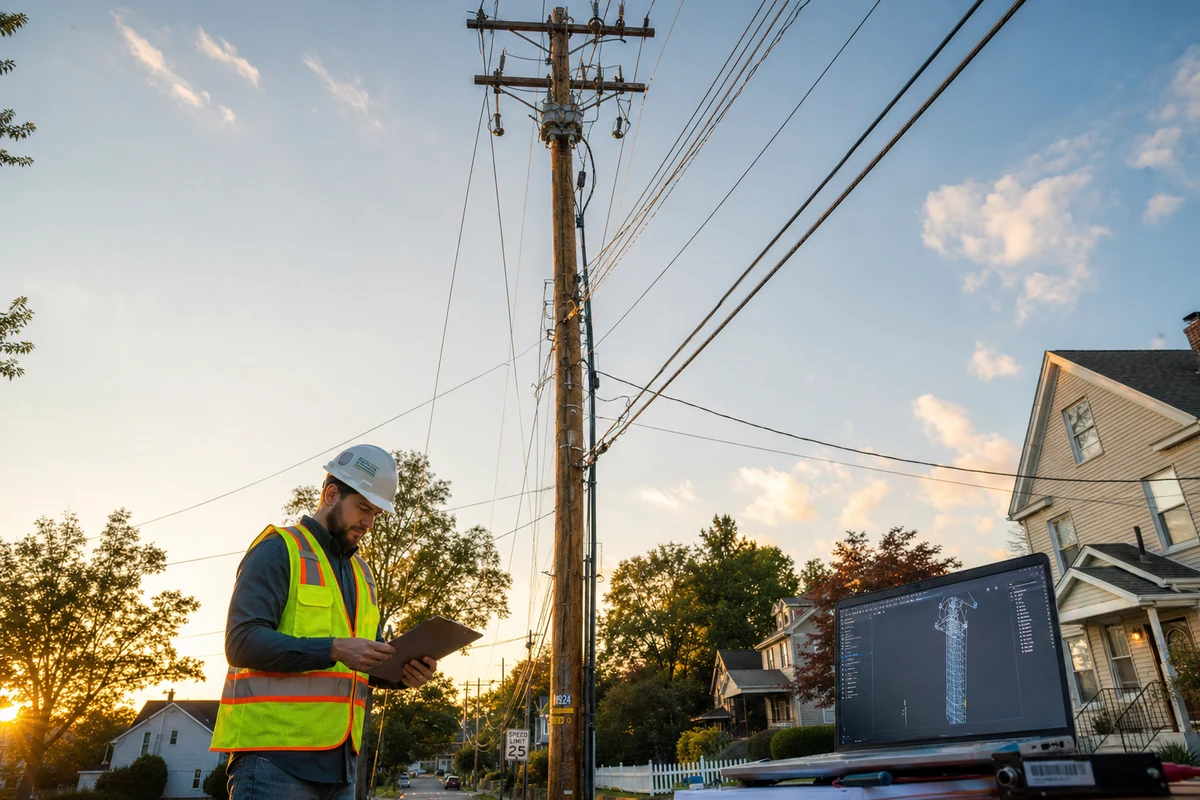
The process starts in the field. A field crew works each pole on the route, collecting the data that the structural model requires: pole height, species (Southern Yellow Pine, Douglas Fir, Western Red Cedar, or other), class, approximate age, condition observations, and the measured attachment height of every existing cable and piece of equipment on the pole. Heights are measured with a calibrated height stick or laser measurement tool — estimated heights are not acceptable for a PE-stamped analysis. The crew also records existing guy wire locations, anchor configurations, and any observable damage like checking, splits, or lean.
That field data gets entered into one of the two industry-standard pole loading software platforms: O-Calc Pro or SPIDAcalc. Both tools build a three-dimensional structural model of the pole, apply NESC load cases to the modeled configuration, and calculate the resulting stress at the groundline. O-Calc Pro is widely used by contractors and engineering firms handling joint-use work for IOUs. SPIDAcalc has strong adoption at cooperatives and among larger utilities that run their own internal analyses. Some utilities have a preferred tool and will require results in a specific format — worth confirming before you start modeling. For a direct comparison of the two platforms, see our breakdown of O-Calc Pro vs SPIDAcalc.
Once the model is built, the engineer adds the proposed fiber attachment — cable diameter, weight per foot, attachment height, span lengths, and hardware — and reruns the analysis. The output shows the before and after capacity percentages for the pole. If any pole exceeds 100% with the proposed attachment, the engineer flags it for remediation and models the remediation scenario to confirm the fix brings the pole back into compliance.
A licensed Professional Engineer reviews and stamps the completed analysis. This is not a formality. The PE review catches modeling errors, confirms that the correct loading district and construction grade were applied, and ensures the attachment parameters match what was actually proposed. Some states require a PE licensed in that specific state — another detail to confirm before starting work if your route crosses state lines.
What the Output Report Looks Like
The deliverable is a PE-stamped report covering every pole in the route. Each pole appears with its structural model summary: pole class and height, species and groundline moment rating, existing attachment inventory, proposed attachment parameters, calculated capacity usage before the new attachment, and calculated capacity usage after. That post-attachment percentage is the number utilities care about most. Under 90% is comfortable. Between 90% and 100% is technically passing but will receive more scrutiny. Over 100% means make-ready is required before the attachment can proceed.
For poles that fail, the report includes a recommended remediation path — transfer, stub, or replacement — and the calculated capacity result after remediation. This lets the utility and the attacher understand exactly what construction is required before the application can be approved, rather than discovering it mid-build.
Joint-use database updates are typically submitted alongside or embedded within the analysis. Utilities that use a joint-use management system such as NJUNS or a proprietary platform expect the pole loading data to feed that system — attachment heights, cable specifications, and loading results all become part of the permanent plant record. Some utilities, particularly larger IOUs, have their own required report templates and will reject submissions that don't conform to their format. We've learned which utilities have specific formatting requirements through years of application work across 22 states, and we build that into every submission package we produce.
The report is submitted as part of the make-ready application package to the pole owner. The utility's engineering staff reviews it, runs their own independent check on flagged poles, and either approves the application or issues comments for revision. Turnaround time from submission to utility response varies widely — some cooperatives move in two to three weeks, some IOUs take 45–60 days. The quality of your analysis package determines how many rounds of comment response you go through.
At Draftech, every pole loading report is PE-stamped and formatted to each utility's application requirements. We've processed thousands of poles across 22 states — and we know which utilities have the longest timelines for approval. Getting the package right on first submission is the only way to avoid adding months to your make-ready schedule.
Who Orders a Pole Loading Analysis?
The party ordering a pole loading analysis is typically the attacher — the ISP, CLEC, cable company, or electric cooperative seeking to add fiber to poles they don't own. In practice, the attacher almost always hires an engineering firm to handle the analysis because it requires licensed PE review and specialized software. The attacher pays for the analysis as part of their make-ready engineering costs. On BEAD-funded deployments, this cost is a recognized eligible expense, but it has to be budgeted correctly upfront — and many subgrantees significantly underestimate it because they don't account for the per-pole nature of the work. Draftech is currently active across 22 states and available to deploy across all 50 U.S. states, which matters on multi-state routes where you need a single engineering partner managing consistent methodology and submission formats across different utility territories.
The analysis is required before a make-ready application can be submitted to the pole owner. That's the sequencing: field survey first, pole loading analysis second, make-ready application third. Some ISPs try to skip or compress the field survey step to save time, which produces analysis errors, which produces utility rejections, which costs far more time than the shortcut saved. There are no shortcuts in this process that actually save time. The data quality drives everything downstream.
Sometimes a second analysis is required after construction. If the as-built conditions differ materially from the design assumptions — a cable was rerouted, an attachment height changed, a span length shifted because a pole location moved — the utility may require a revised analysis confirming the as-built configuration still complies. This is more common than most ISPs expect, especially on rural routes where field conditions don't match GIS data and construction crews make real-time decisions that aren't always captured in the as-built record.
Cooperatives, investor-owned utilities, and municipal systems all require this analysis — the requirement is universal for aerial attachments. The specific format and submittal process varies, but the underlying engineering work is the same. If you're building across multiple utility territories on a single route, you'll often be dealing with two or three different submittal formats and review timelines simultaneously, which is one of the practical reasons ISPs use a dedicated engineering firm rather than trying to manage this in-house.
For more on how to evaluate and select an engineering partner for this work, read our guide to hiring a pole loading engineering firm.
The Make-Ready Connection
Pole loading results are what determine make-ready scope. This is the relationship that project managers most often underestimate before they've been through a full aerial fiber build.
Here's how it works in practice. A utility pole sitting at 75% of its allowable capacity before your fiber cable is added has plenty of room. Add a standard 144-fiber loose-tube cable at the communication space attachment height, and the post-attachment capacity might come in at 82%. That pole passes without any make-ready required. Move that attachment to a pole that's already at 85% capacity — not unusual on routes with multiple existing cable TV, telecom, and strand attachments accumulated over decades — and your fiber pushes it to 94%. Still passing, technically, but the utility may require rearrangement of existing lower attachments to maintain required clearances. That rearrangement is make-ready work, billed to you.
Now consider a pole at 91% that goes to 104% after your fiber is added. Over 100% means the pole cannot support the attachment as proposed. The utility requires remediation before approval. Your options are transfer (moving one of the existing attachments to another pole or rerouting to eliminate it), stub pole installation alongside the existing one, or full pole replacement. Replacement runs $4,000–$8,500 installed, depending on class, terrain, and location. On a 400-pole route, if 18 poles require replacement — not an unusual result on an old rural plant — you're looking at $72,000 to $153,000 in pole replacement costs that weren't in your original budget.
This is exactly why make-ready cost estimates based on per-mile averages are so often wrong. The actual cost is determined pole by pole, and you don't know the pole-by-pole result until the loading analysis comes back. ISPs who build their make-ready budget before they have field data and analysis results are guessing, and the guesses are usually low.
The loading analysis is also what drives make-ready timelines. A pole requiring transfer involves scheduling the affected attacher's crews, which adds weeks. A pole requiring stub installation needs a construction permit and utility coordination. A pole requiring replacement needs to be ordered — and pole material lead times in some regions run 10–16 weeks. You cannot compress that schedule by working faster. You can only compress it by doing the loading analysis early enough in the project timeline that pole procurement and construction scheduling happen before your installation crews are standing in the field waiting. For a detailed breakdown of timeline impacts, see our article on make-ready engineering timelines for fiber deployment.
The specific dollar figures vary by region, terrain, and material costs, but our guide to make-ready cost per pole covers what to budget across the different remediation scenarios. If you're working on a BEAD project, that article also covers how make-ready costs factor into your eligible expense documentation.
The short version of everything above: run the pole loading analysis before you commit your construction budget numbers. The analysis is not the expensive part. The surprises discovered after you've committed are the expensive part.
Our pole loading analysis services cover field data collection, O-Calc Pro and SPIDAcalc modeling, PE stamp and review, and utility-formatted submission packages. If you have a project in planning or have already received a utility rejection and need to understand what remediation will require, reach out at info@draftech.com or call 305-306-7407.