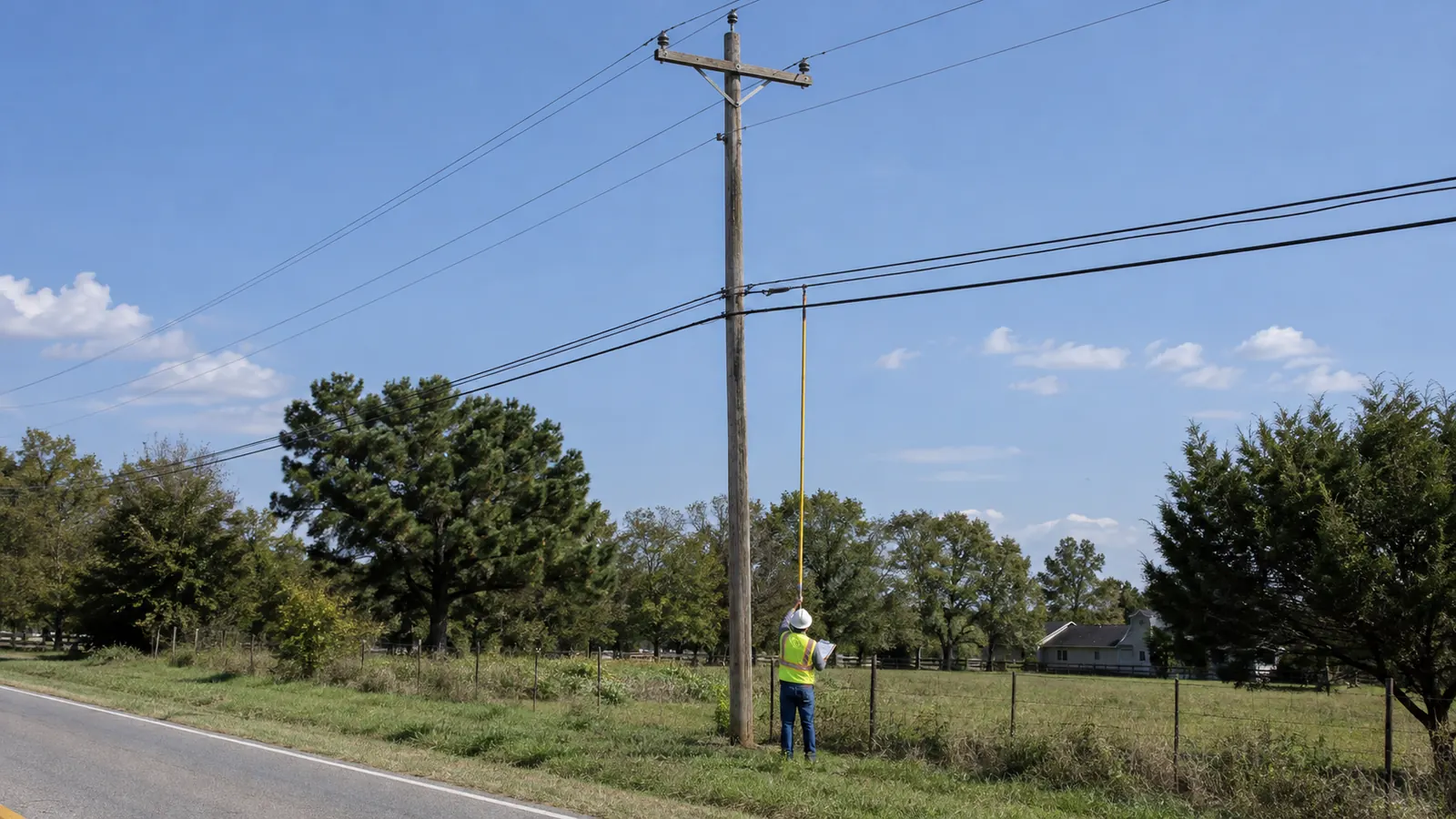
Open wood below the power lines can look like room for fiber. We check the entire pole assembly and adjacent spans, starting above the proposed attachment and working down to the ground.
Parts of a utility pole: a top-to-bottom view
The parts of a utility pole form 2 working spaces on a typical joint-use distribution structure: electric supply above and communications below. Between them sits the communication worker safety zone. Crossarms and insulators support energized conductors; lower attachments support communications cables, while guys and the embedded pole transfer loads into the ground.
Pole arrangements vary. A single-phase lateral may look very different from a circuit with multiple primary conductors and pole-mounted equipment, even when both carry the same proposed fiber route. We identify the actual construction before assigning attachment heights. A silhouette cannot establish voltage or ownership.
Primary conductors, crossarms and insulators
Primary conductors carry distribution power toward transformers. They may sit on a crossarm or use other supported arrangements, so we record their actual positions rather than drawing every pole with the same horizontal assembly. Insulators electrically separate energized conductors from supporting hardware. Crossarms and braces carry the resulting forces back to the pole through their connections.
Height changes the bending effect. Wind acting on a conductor high above ground produces a different ground-line moment from the same force applied lower down, and conductor tension can introduce substantial unbalanced loading where a line turns or ends. We need the span geometry and conductor information to model that effect. Counting visible wires alone leaves the engineering incomplete.
Crossarm condition also matters. We document a split member or displaced brace for owner review, even when the proposed attachment sits below the supply space. Required repairs can affect make-ready sequencing.
Neutral, secondary and transformer equipment
The neutral often runs below the primary conductors, but its placement depends on the distribution system. It remains an electrical facility. Secondary conductors carry power from a transformer toward customer services, and bundled construction can make them resemble communications cable from a poor viewing angle. We trace connections where visible and flag uncertain identification for the owner.
A transformer changes both the available space and the structural model. Its weight acts through its mounting hardware, while wind acts on the equipment's exposed area; an offset mounting can also affect how those forces reach the pole. We record the equipment and its location. The attacher cannot assume that lowering a proposed cable resolves every conflict around the transformer.
Risers and the occupied pole face
A riser takes a cable between overhead and underground facilities, often within protective conduit along the pole. Supply risers and communications risers require different treatment. We follow the visible route and identify the facility owner before proposing work near it, because a conduit occupying the intended mounting face can change a workable attachment detail.
A side view can reveal a hidden riser. We capture the proposed mounting face and include riser stand-offs in the equipment inventory when their loads affect the analysis.
The safety zone and communication space
The communication worker safety zone separates the supply space from communications attachments. We treat it as a defined design boundary. The National Electrical Safety Code, 2023 Edition, IEEE C2-2023, published August 1, 2022, addresses separation between supply and communications facilities; the applicable adopted edition and pole-owner requirements must govern the specific attachment.
Clearance depends on the facilities involved. A measured gap in one photograph cannot establish compliance throughout a span, where conductor sag and the required design conditions can produce a different separation from the gap at the pole. We retain the measured positions and identify the applicable requirement in the design review. We do not assign a universal clearance to every arrangement.
The lower-pole observations answer different engineering questions.
| Observation | Field record | Engineering use |
|---|---|---|
| Safety zone | Supply-to-communications relationship | Determine the applicable separation requirement |
| Strand and cable | Supported bundle and attachment height | Model the proposed added load |
| Attachment order | Owner and elevation of each facility | Define rearrangement dependencies |
| Guys and anchors | Attachment direction and anchor lead | Evaluate the resisting load path |
| Ground wire | Visible routing and bonding connections | Identify conflicts with proposed hardware |
| Pole and ground line | Markings, embedment evidence and condition | Establish structural inputs |
Strand and lashed cable
Messenger strand provides mechanical support for cable lashed to it. The lashing wire secures the cable to the strand along the span. We distinguish the messenger from the supported cable in the inventory because their properties and structural roles differ, and the complete bundle determines the loading assigned to that attachment.
Overlashing adds material to an existing supported bundle. It changes weight and exposed diameter without necessarily creating another attachment level, which is why a pole-face sketch can understate the change if it shows only attachment elevations. We ask for existing and proposed cable information before treating the available strand as suitable. The supporting strand still needs evaluation.
Cable identification has limits. We can document visible dimensions and routing, but a jacket seen from the ground may not establish the exact product or installed tension needed by the model. Our limitation is that a visual inventory cannot recover concealed properties or prove every record current. Missing information stays identified until records or an accepted engineering assumption resolve it.
Existing attachment order
The communication space can hold facilities belonging to several attachers. There is no universal rule that every fiber cable belongs above every coaxial cable or every telephone cable. We record the actual top-to-bottom order and associate each attachment with its owner, using confirmed records where visual identification falls short.
Order affects the work sequence. Moving an upper cable may require access around a lower attachment, and lowering a cable can create a ground-clearance problem that was absent at its existing height. We compare the proposed arrangement with the adjacent poles before calling the move feasible. A single pole elevation cannot describe the full span.
Existing closures and slack storage need room too. We include their support hardware in the survey and distinguish cable passing through from cable ending at the pole, because termination forces and local equipment loading can change the proposed remedy. An apparently abandoned cable remains an existing attachment until its owner authorizes removal.
Turning an inventory into a loading review
Our pole loading analysis explainer follows the calculation beyond the component names. Identifying occupied space and establishing structural capacity require different evidence.
When the field record shows a crowded communication space or uncertain equipment loading, our pole loading analysis service evaluates the existing and proposed arrangements using the required design inputs. We keep the loading result tied to the same attachment schedule used for make-ready. A passing calculation for the wrong arrangement gives the construction team no usable decision.
Guys, anchors and the ground wire
A down guy transfers a portion of the pole's loading to an anchor. It commonly addresses the pull created by a line angle or dead-end, but the actual assembly must match the forces it is intended to resist. Follow its direction. We record where the guy attaches and where its anchor sits relative to the pole.
Guy direction and anchor lead
Anchor lead is the horizontal distance from the pole to the anchor. Together with the guy's attachment elevation, it establishes the guy angle and affects the tension needed to resist a given horizontal force. A guy pulling in the wrong direction cannot be credited as though it opposed the proposed cable's load.
The anchor depends on soil resistance. A visible rod cannot establish the buried assembly's type or capacity, so we may need owner records or a separate assessment before the analysis can rely on that anchorage.
Shared support requires deliberate review. An existing supply guy does not automatically provide adequate support for a new communications load merely because both connect to the same pole. We identify the load path through the actual fittings and anchor assembly, then establish whether the proposed arrangement is acceptable to the owner. A replacement anchor also needs a buildable location.
Photograph the guy's full path and anchor location in the same survey record as its attachment height. A close-up of the pole connection alone leaves the engineer guessing about the direction in which the guy can resist load.
Ground wire and bonding
The ground wire commonly follows the pole vertically toward a grounding electrode. It serves an electrical purpose rather than the bracing function of a guy, even when both appear as exposed wire in a photograph. We document its route and visible condition. Communications bonding connections also deserve attention when rearrangements affect existing hardware.
A damaged or displaced ground wire needs the facility owner's attention. We avoid treating it as something an attacher can casually shift to make room for a bolt, and the work plan must identify who is responsible for any authorized change. Its contribution to structural loading is generally small compared with conductors, but its position can still control an attachment detail.
Pole markings, class and setting depth
The pole's identification tag connects the field observation to the owner's asset record. The manufacturing brand, sometimes called the birthmark, describes the wood pole itself. They serve different purposes. We photograph both when present and preserve the distinction in the survey so the loading model and application refer to the same structure.
Reading the tag and birthmark
A manufacturing mark may identify class and original length, with species and the year of treatment or manufacture shown under the applicable marking convention. The year needs interpretation. It should not silently become the installation year in the asset record, because storage before installation and later replacements can make those dates different.
A weathered brand can leave an ambiguous character. We keep an unreadable value marked MISSING and seek the owner's record instead of choosing a class that makes the model pass. Check the asset number too. A readable brand associated with the wrong pole produces the wrong loading case.
Classes and heights, briefly
Pole class describes a standardized strength classification; nominal length includes the buried portion. Neither alone establishes spare capacity for a new attachment. We use the ANSI O5.1 pole specifications guide for the detailed relationship among class, dimensions and wood species, then apply the identified pole properties to the actual loading model rather than repeating a class table here.
Setting depth and ground-line condition
Setting depth is the portion of the pole embedded below ground. It affects exposed height and the support available from the surrounding soil, so a nominal length in a brand cannot be used directly as the above-ground height in a clearance review. The ground line matters. Grade changes can also complicate comparison with an older installation record.
For reference dimensions, Utility Pole Charts provides free charts of minimum wood pole circumference, diameter, setting depth and class load by species, class and length, from USDA RUS Bulletin 1724E-150, Unguyed Distribution Poles: Strength Requirements (2014), using ANSI O5.1 minimums. We treat the charts as reference information. They do not measure the installed depth or establish the condition of a particular buried pole.
Visible lean and deterioration deserve separate attention. A stronger nominal class does not erase decay near the ground line, and a drawing's assumed embedment cannot prove what remains after erosion or grading. We record observable conditions and refer unresolved structural condition questions to the owner's inspection process before relying on the pole for the proposed attachment.
Using the parts of a utility pole in make-ready decisions
For field survey teams: return a pole record that connects each attachment to an identifiable elevation and owner. Include views of the pole faces that the main photograph hides. We prioritize resolving uncertain cable identification before design, because a misidentified supply facility changes the permitted work scope and can invalidate a communications rearrangement.
For attaching network owners: require the proposed attachment schedule to match the loading submission. Ask which existing facilities must move and whose authorization each move needs before treating the route as ready for construction. We recommend documenting those dependencies pole by pole. That gives the project manager a practical basis for sequencing work instead of relying on a route-wide assumption.
For pole-owner reviewers: return unresolved condition or asset-record questions with the affected pole identified. Identify required work before accepting the proposed arrangement, so the eventual installation can be checked against that approved condition.
Draftech International provides turnkey telecom and power infrastructure, with engineering performed 100% in-house and full turnkey construction delivered by Draftech-managed subcontract crews. Our partner and company information identifies the team behind that work. We connect the surveyed hardware to the loading model and make-ready scope so missing pole properties and conflicting attachment schedules are addressed before the construction handoff.
For a qualifying route, Draftech engineers the first 20,000 linear feet at no cost, from feasibility and field survey through permit approval. Submit the route through our free engineering design offer; the owner reviews each request before Draftech commits the package. Email Draftech to discuss your pole attachment project.