A ceiling antenna tells a building owner very little about whose customers can use it. The difficult decision comes earlier: which carriers will participate and who will keep the shared system working after occupancy changes.
We approach indoor cellular design by establishing those commitments before drawing antenna locations. A shared distribution network can reduce duplicated infrastructure, but the building still needs a workable arrangement with each participating carrier. That distinction shapes both the radio design and the owner's operating obligations.
What a neutral host distributed antenna system does
A neutral host distributed antenna system is shared indoor cellular infrastructure that distributes signals for 2 or more participating carriers through antennas placed around a building. Each carrier supplies or approves its connection to the system, while the shared distribution equipment carries its signals to the areas the venue needs covered.
The word neutral describes the hosting arrangement. It means the infrastructure can serve multiple operators rather than being reserved for the exclusive use of a single carrier. It does not mean every mobile subscriber automatically receives service. The participating networks and supported frequency bands determine what the system can deliver.
Follow the signal from source to phone
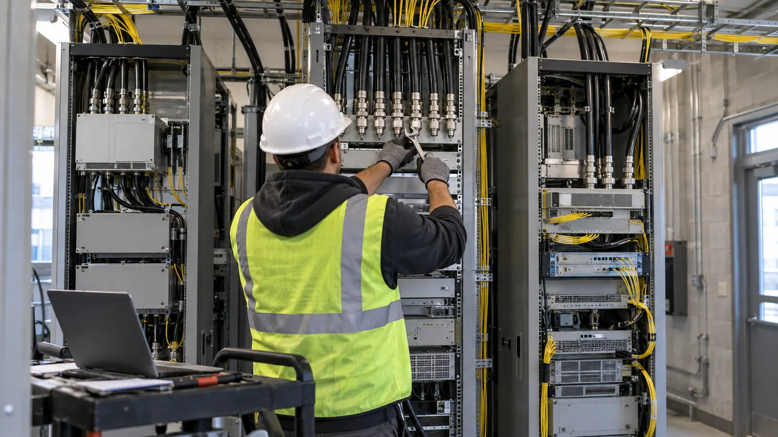
At the headend, carrier signal sources connect to the distribution system through interfaces selected for that architecture. An active DAS commonly transports signals over fiber to powered remote units near the coverage areas. Those units feed indoor antennas, sometimes through short coaxial branches. The return path carries transmissions from handsets back toward the carrier equipment.
We separate the signal source from the distribution network on the drawings because a source provides the cellular service and associated capacity, while the DAS distributes that service. Adding antennas can improve where the signal reaches, but distributing the same source more widely does not automatically increase the traffic it can support.
Shared equipment, separate carrier decisions
Carriers can share distribution hardware while retaining separate spectrum and network connections. The architecture must support the agreed bands and interface requirements, and the design must protect each participant from interference or incorrect signal levels. A shared system can still require carrier-specific equipment at its headend.
Who owns the decisions and ongoing obligations
The owner sets service expectations. That includes deciding whether cellular coverage must extend into service spaces and how future tenants will be accommodated. Floor plans cannot answer those questions. We need an agreed coverage boundary before predicting performance against it.
Venue owner and neutral host
The owner controls access to the building and approves the use of equipment rooms and pathways. The neutral host typically coordinates the shared infrastructure and the participating operators, with ownership and maintenance duties established by contract. Sometimes the owner takes that role directly; sometimes an independent organization does. We keep those commercial roles explicit without assuming that ownership determines who performs every task.
Small Cell Forum's announcement, “Small Cell Forum neutral hosts propose Hosted Open RAN global framework,” published July 13, 2021, describes neutral hosting across architectures that include DAS and small cells. That distinction matters here: neutral host is an operating model, and the owner still has to choose the technology that fits the venue.
Carriers and the design team
Each carrier evaluates its participation and the technical connection to its network. Its review can affect the supported bands or the source configuration. The neutral host coordinates those reviews, while the designer translates accepted requirements into a buildable distribution layout. We show unresolved assumptions plainly because a late carrier change can affect equipment space and power demand.
Draftech designs in-building DAS with engineering performed 100% in-house. Where a project needs coordinated RF planning and building pathways, our wireless engineering for in-building coverage brings those design decisions together. The DAS design scope should identify the deliverables and the carrier information required to complete them.
Comparing DAS hosting models with small cells
Start with who needs service. A tenant using a single contracted mobile network presents a different problem from a public venue whose visitors arrive with subscriptions across several networks. We compare the alternatives against that demand before treating shared infrastructure as a purchasing preference.
| Decision | Neutral host DAS | Single-carrier DAS | Small cells |
|---|---|---|---|
| Operator participation | Multiple participating carriers | A defined carrier | Single or multiple operators, depending on architecture |
| Radio function | Distributes connected signal sources | Distributes the selected carrier's source | Provides cellular radio access through local nodes |
| Building coordination | Shared pathways with carrier interfaces | Fewer carrier interfaces initially | Node locations and network transport need coordination |
| Capacity planning | Source and sector design determine capacity | Capacity follows the selected source | Cell layout and backhaul shape available capacity |
| Expansion question | Can another carrier or band be accommodated? | Can the system support a broader requirement? | Can more nodes or operators join the accepted architecture? |
When shared distribution earns its place
Large buildings with a mixed subscriber population are strong candidates for a neutral host assessment. Shared pathways can avoid repeating a full indoor distribution build for every carrier. We still test the business case against actual participation, because reserved space and unused capability can become costs the venue carries for years.
Our preference for coordinated infrastructure has a limitation: we can overdesign for future carriers if their participation is treated as certain. A better design separates committed needs from expansion provisions, since spare pathway capacity may be sensible even when buying an additional remote unit would be premature. Estimate those choices separately.
High attendance also changes the calculation. A venue may need separate service sectors to keep a concentrated audience from overwhelming a shared source. The discussion of DAS coverage and capacity in busy venues develops that problem further. A floor area estimate by itself cannot represent the load of an occupied event space.
When a single-carrier system is sufficient
A single-carrier DAS fits a defined operating requirement where the intended users have service from that carrier. Narrower participation can simplify coordination. We would choose it for that reason only after the owner confirms that visitors on other networks fall outside the intended service commitment.
Retain the accepted carrier configuration. The owner should keep it with the building records. That gives a future facilities team a clear starting point when a tenant requests coverage from a different network.
Where small cells deserve consideration
Small Cell Forum's “About small cells” overview defines a small cell as a low-power radio access point and discusses multi-operator implementations. A small-cell design can concentrate capacity where users gather, and a neutral host arrangement can apply to small cells too. The choice is therefore broader than shared DAS versus a collection of isolated carrier boxes.
For a contained indoor area, we evaluate whether local radio nodes offer a practical coverage and capacity solution with acceptable transport requirements. Our explanation of how a small cell supplies cellular service helps distinguish that approach from distributing a separate source. Both paths require operator acceptance. A generic multi-operator capability statement cannot settle it.
Design a neutral host distributed antenna system around the building
An RF prediction starts with a representation of the building, but existing drawings can omit changes that affect propagation. We check the current floor layout against the intended occupancy and identify materials likely to block signals. The model needs a field basis. A recently enclosed room can matter more than a neat architectural background.
Coverage criteria and radio performance
Coverage objectives need measurable acceptance criteria. The participating carriers must agree to them. We identify the required bands and the areas to be tested, then document the signal-quality measurements that will be used. A single universal signal-strength threshold would hide differences between service requirements and could create an acceptance dispute after construction.
The uplink deserves its own calculation. A handset has to reach the network through the return path even where the downlink looks strong. We review the noise contribution of the distribution system and the gain arrangement, considering how the proposed configuration affects the carrier's receiver rather than judging the design by a coverage color alone.
Passive intermodulation is another design concern: unwanted mixing products from nonlinear passive components can impair reception. Component choices affect that risk. Connection quality matters, too. We specify appropriate performance requirements in the design package and identify the tests needed to assess the completed system. Built conditions determine the final results.
Keep the model tied to occupancy: Ask the owner to identify rooms whose use is expected to change before the antenna layout is finalized. A partition change should trigger a review of the affected coverage area.
Fiber routes and equipment space
Remote locations must work physically. We check its access and mounting conditions against the building layout, including the cable route back to the headend. Where vertical pathways carry the distribution backbone, riser cable design for multi-story buildings explains the coordination needed between floor access and the backbone route.
The headend needs space, too. Its layout must accommodate the accepted source arrangement. Power and cooling requirements follow the equipment actually selected, including any planned growth the owner elects to fund. We avoid assigning a generic equipment-room allowance before the participating carriers have defined their interfaces; that shortcut can make a later layout impossible to fit.
Sector boundaries and future changes
Occupancy should guide the distribution layout. A conference floor may need a different sector arrangement from a corridor, even when both have similar measured signal levels. We align source capacity with expected demand and show which antennas belong to each service area so the operating team can understand later changes.
Acceptance, maintenance, and the owner's next decision
A building should be accepted against its agreed service criteria. We recommend a test plan that identifies each participating carrier and the areas included in the assessment. Record the test conditions. This matters particularly where occupancy affects performance. A quiet-building walk test cannot by itself demonstrate capacity during the venue's busiest use.
Make the service boundary testable
The acceptance record should connect the measured results to the installed antenna and sector arrangement. Deviations from the design need to be evaluated before the final record is issued. If an antenna moves because the ceiling is inaccessible, we want the changed location assessed rather than leaving the original prediction attached to a different physical system.
Commercial cellular coverage and public-safety radio coverage require separate scope decisions. A venue should never assume that acceptance of its cellular DAS establishes compliance for emergency responder communications. We ask the owner to identify the applicable public-safety requirements with the responsible authority and coordinate the designs where they share building space.
Plan for fault isolation: Give the operating team a clear boundary between the shared distribution system and each carrier's connection. An alarm needs an assigned responder even when its cause falls outside the neutral host's equipment.
Choose the next step by the service you need
Public venue or multi-tenant owner: Begin with carrier engagement and a building survey. Use the resulting commitments to compare a shared DAS with a neutral host small-cell design. We recommend reserving expansion space deliberately, with a stated purpose for each allowance, so the initial investment supports confirmed service without purchasing every possible future configuration.
Organization with a defined single-carrier requirement: Evaluate a single-carrier system against that requirement first. Confirm the user population and document what happens if the mobile contract changes. A simpler participation model can be appropriate, provided the owner accepts its service boundary and understands the engineering needed to broaden it.
Owner addressing a localized indoor gap: Assess small cells before committing to building-wide distribution. Identify the required operators and the transport available at the proposed node locations. We recommend expanding the assessment to a shared DAS when the actual coverage boundary or coordination burden justifies it, rather than treating building size as an automatic trigger.
Draftech's in-house DAS design work connects the carrier interfaces to the building's physical constraints, so antenna predictions and equipment layouts describe the same project. Email us the current floor plans and intended carrier coverage or use our contact form; those inputs let us resolve the uncertainty around the headend and interior pathways before it spreads through the design.
If the building's connectivity work also requires an outside fiber route, Draftech's free route engineering offer covers the first 20,000 linear feet of a qualifying route at no cost, from feasibility and field survey through permit approval. The owner reviews each request before Draftech commits the package, so the route scope can be assessed separately from the indoor DAS design.