In This Article
What fttn means for the outside plant
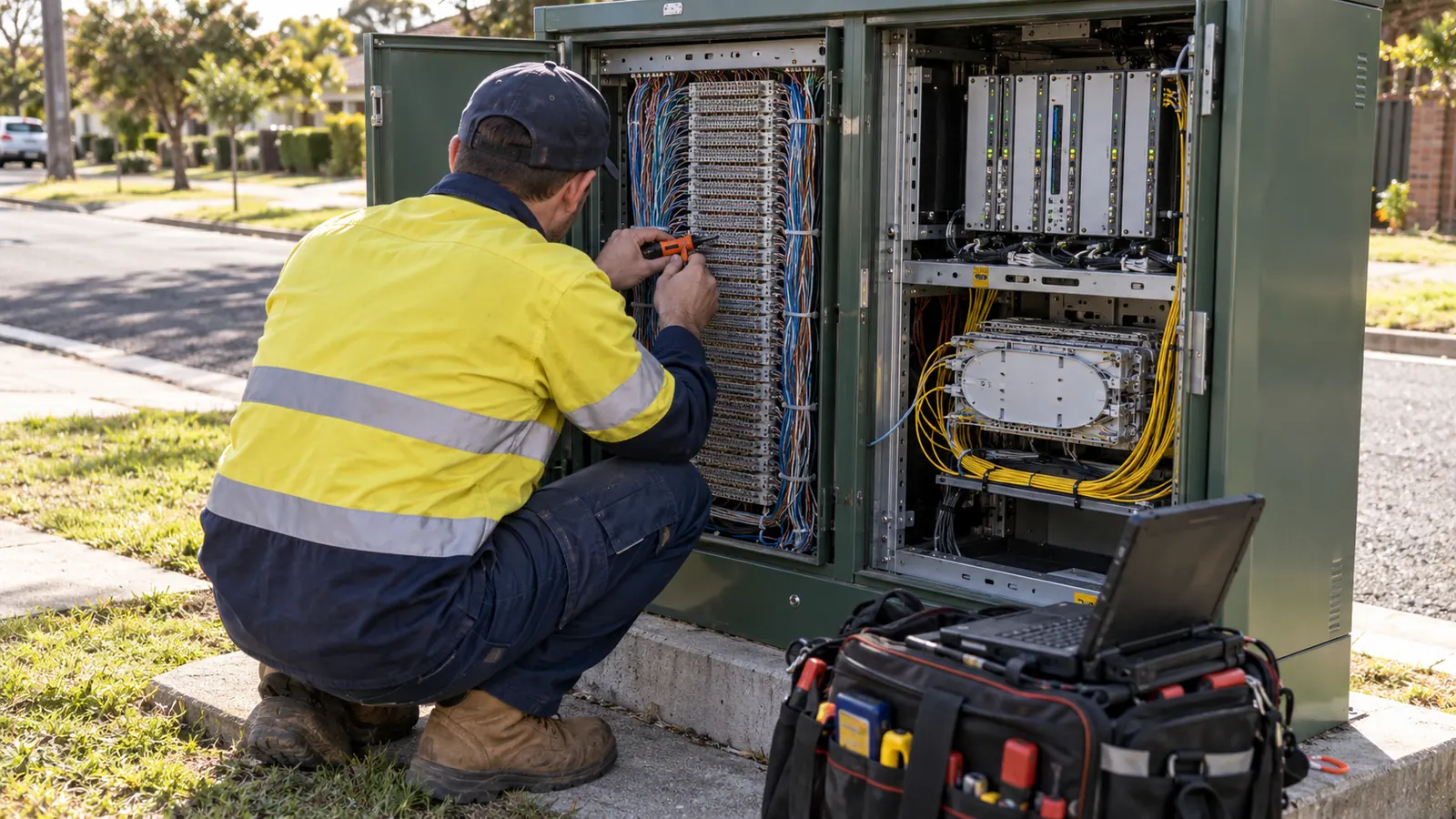
Fiber to the node, or fttn, brings fiber to a powered street cabinet and uses existing copper pairs for the final connection, running VDSL2 or G.fast under ITU-T G.993.2 and G.9701. The design must match node placement to copper loop length and preserve a practical path toward fiber to the home.
A cabinet can sit close to a property while its serving copper takes a much longer route. For that reason, we start by tracing the actual pair path: a short distance on a map can conceal a cable that doubles back through a distant cross-connect before reaching the subscriber. Moving fiber toward that subscriber helps only if the retained copper connection becomes suitable for the intended service.
For a telco, ISP, co-op or municipal network that owns copper plant, the useful question is how much of that plant deserves another active service stage. We treat node placement as part of the eventual fiber layout. A convenient site can become a constraint if its feeder ends away from the future distribution network or if the site agreement prevents expansion.
VDSL2 and G.fast describe transmission, not the serving boundary
ITU-T Recommendation G.993.2, Very high speed digital subscriber line transceivers 2 (VDSL2), edition 02/2019, approved 02/22/2019, defines VDSL2 operation over twisted pairs. Its summary includes deployment from fiber-fed cabinets. The standard identifies the technology; we still need the operator's selected profile and measured line conditions to judge whether a proposed cabinet serves the intended addresses.
For G.fast, the relevant standard is ITU-T Recommendation G.9701, Fast access to subscriber terminals (G.fast) - Physical layer specification, edition 03/2019, approved 03/22/2019. The in-force recommendation includes subsequent amendments and corrigenda. For an outside-plant package, we ask the operator to identify the applicable equipment requirements before accepting a retained loop, particularly where the proposed service depends on bringing fiber very close to the premises.
Neither name supplies a universal speed for a street. Longer loops generally reduce attainable rates. Noise and pair condition also matter, so we avoid drawing a service boundary around a headline throughput figure when the underlying copper evidence has not been checked.
Keep the architecture names separate
FTTC brings fiber to a curbside distribution point with a short remaining connection, commonly copper. FTTB brings fiber into a building and uses the selected internal distribution medium to reach individual units. FTTH carries fiber to the home, removing the outside copper pair from that access connection.
On the network drawing, we mark where fiber stops and the retained medium begins so the handoff is clear to the next person reviewing the design. An address list should identify which premises remain on copper after the node work and which belong to a later optical distribution area, so a migration planner can follow the same service boundary without reconstructing it.
Place fttn nodes around the copper serving area
Before choosing cabinet positions to survey, we trace the serving cable and reconcile its physical route with the pair assignments. Confirmed connections can then be separated from records that still need field verification. Even with accurate address coordinates, an unexplained branch can change how far the candidate node reaches.
Measure the remaining loop
Measure loop length along the electrical path from the proposed access equipment all the way to the subscriber termination, including the retained drop. A road-centerline distance or a radius around the cabinet misses deviations in the distribution cable, and it can hide the very premises that are hardest to serve after the fiber extension.
Our starting record pairs each address with its proposed node and the evidence behind its loop length. Where route drawings disagree with line records, mark the connection unresolved rather than averaging the distances. The operator can then target testing where it affects the siting decision instead of collecting another set of measurements that cannot be tied to an address.
Pair condition changes the choice. A short route with damaged joints may need intervention before the operator can rely on it for service. Bridge taps or loading coils can also affect DSL suitability. We keep those findings attached to the serving cable, with the operator responsible for determining the line treatment and access equipment configuration.
The audit boundary is explained further in our legacy copper plant engineering guide. For this decision, the output should distinguish usable retained plant from plant whose condition remains unknown. We leave unknown loops flagged in the record, even when adjacent pairs in the same cable sheath have passed. Those results cannot establish the condition of a pair that still needs checking.
| Design decision | Evidence required | Reason to revise the node plan |
|---|---|---|
| Copper serving area | Address-to-pair mapping and remaining loop paths | Remote or unsuitable pairs remain inside the proposed service area |
| Cabinet site | Surveyed footprint and confirmed occupation rights | Access or future expansion conflicts with the available space |
| Power and backup | Operator load schedule and utility supply requirements | The site cannot support the required operating arrangement |
| Feeder allocation | Current transport assignment and future FTTH demand | Reserved fibers do not connect to the planned optical distribution |
| Migration boundary | Service dependencies and staged acceptance criteria | Retiring copper would disconnect a service that remains active |
Whenever the node moves, we recalculate the loops for the affected addresses before carrying the service assumptions forward. If a permit constraint shifts the cabinet to the opposite end of the serving area, the original service assumption may no longer hold, even though the new location looks equivalent on the civil plan.
Settle cabinet siting and permits before fixing the feeder
To assess whether a cabinet location is buildable, we survey the space technicians will use as well as the equipment base. That includes the door swing and room for battery replacement. A cabinet may fit between existing features yet obstruct the surrounding corridor as soon as someone opens it for maintenance.
Survey the site as an operating location
Confirm the cabinet's supplied dimensions against the surveyed site and the owner's requirements. The review must account for drainage and exposure, with the equipment supplier defining environmental operating limits. Where vehicle impact protection is needed, its layout should be coordinated with access rather than added after the cabinet footprint has already been approved.
Maintenance access must remain workable after the build. We check how a technician reaches the cabinet and where a service vehicle can stop without obstructing the work area. If the preferred approach crosses private land, the access right needs to cover that activity; a route permission for buried cable may not grant permission to occupy the surface with equipment.
The future overlay belongs on the site sketch now. Show the passive fiber facilities that might remain when the active cabinet is retired, then check whether their access can be maintained independently of the copper enclosure. Sharing the space makes sense where both facilities remain accessible, but we would reconsider the arrangement if cabinet removal would disturb the permanent feeder or block the new distribution entrance.
Give each approval a defined footprint
The permit register needs separate entries for the cabinet occupation area and feeder route because each may be controlled by a different owner. A right-of-way approval can cover a cable alignment while a separate property agreement controls the cabinet site, and the design needs both before it treats the location as available for construction.
Coordinate the power-service approach with those boundaries before issuing the final drawing set. A utility-required meter position or supply trench may change the site layout. The permit package should show the actual arrangement under review, including restoration limits where applicable, so an approval does not depend on a power route that later proves unavailable.
Our FTTH overlay design work connects these site decisions to the eventual distribution layout. We use that future layout to test whether the proposed node location can serve a lasting purpose after the copper stage. The cabinet itself may disappear; the useful asset can be its permitted corridor and an accessible fiber splice location nearby.
Define power and backup responsibilities at the node
Before we fix the power-service arrangement or reserve backup space, the operator needs to supply a load schedule for the selected equipment, including environmental controls. The active cabinet depends on electrical power even though fiber feeds it, so the site design must also accommodate the operator's plan for a supply outage.
Use the operator's load and resilience requirements
Equipment configuration and operating conditions affect the load, while temperature and aging change the battery capacity available to support it. Backup autonomy therefore needs a stated load basis and usable battery capacity, with the operator or equipment specialist confirming the required performance rather than treating the enclosure's available battery space as proof of runtime.
For site planning, we ask whether the operator intends to use fixed backup equipment or a portable response, then check the access each approach requires. A portable supply arrangement needs a safe connection location and a way to reach the cabinet during the conditions that caused the outage, subject to the owner's electrical and operating requirements.
Assign the interfaces explicitly. The serving utility establishes its supply requirements, and the operator owns the access-equipment specification and backup objective. Our outside-plant drawings coordinate those inputs with the cabinet site and cable route. That division keeps a civil design assumption from turning into an unsupported promise about electronics or service availability.
Keep power revisions tied to the site plan. If the supplier changes the cabinet load or backup footprint, reopen the affected site review before releasing construction drawings. A replacement enclosure can fit on the same base yet require a different service approach or working area.
Once power returns, the acceptance review still needs to establish whether subscribers have service again; we keep both questions in the handoff requirements. The operator should verify service after the node returns to normal operation, while the construction record documents the installed site arrangement and any approved departures from the issued drawings. A closed civil punch list cannot establish that every retained copper service has recovered.
Design the feeder for a later FTTH overlay
An allocation drawing should show where the feeder fibers will go for both the present node and the intended optical distribution. We mark the active-node transport assignments separately from the overlay reservations. Tracing both through the upstream splice points lets us check whether those connections are possible before selecting the cable capacity.
Count the fibers the selected architecture requires
To establish the strand count, we use the feeder demand of the future optical architecture rather than infer it from the number of copper pairs in the serving cable. We develop that allocation against the operator's chosen distribution boundaries and protection requirements, accounting for the places where current and future service must coexist during migration rather than assuming an immediate swap.
Check splice capacity at every planned branch. A large cable passing the cabinet helps little if the assigned fibers cannot be accessed there or the closure cannot accommodate the intended connections. Our drawings carry the assignments into the splice schedule so the reserved capacity survives the transition from a planning diagram to an installable package.
Beyond the fiber allocation, we check the route for available duct space because a cable with spare strands may still occupy the only usable pathway. If the overlay later needs another cable, the design should establish whether an available pathway reaches the future distribution area and whether its occupation rights permit that use; the answer may favor a different feeder alignment before anything is installed.
Reserve a usable connection. Identify the future branch location and the fibers that reach it. Labeling a cable with spare capacity leaves the essential question unanswered if every spare continues past the place where the overlay must begin.
Keep the migration sequence visible
Comparing the copper and future FTTH layouts sometimes exposes a limitation of our staged approach: a cabinet that reaches the copper subscribers may sit in the wrong place for optical distribution. Where they disagree, retain the useful feeder corridor and place the future passive distribution elsewhere instead of forcing the optical network to inherit every copper boundary.
The copper-to-fiber migration engineering process carries that decision into service sequencing. Each cutover group needs an identified destination and an operator-approved acceptance condition before its old connection is released. We review special service dependencies individually, since marking a premises record migrated must not authorize removal of another active circuit sharing its route.
For removal work to remain traceable after migration, our splice layout distinguishes the permanent connections from those needed only while copper and fiber coexist. The receiving operations team should be able to tell which connections remain permanent, which supported the transition, and what evidence is required before the redundant copper or active-node facilities can be taken out of service.
Check the feeder from both ends. At the upstream end, confirm that the assigned fibers terminate where the operator can provide the intended transport or optical access connection. At the node end, confirm that the same assignments reach the planned splice location without relying on fibers already committed to another service. An unbroken line on a route drawing can otherwise conceal an unavailable connection inside an existing closure.
Construction changes must return to the allocation record. We want the final route and splice information to reflect what was installed, especially when an obstruction moves a closure or forces a different cable entrance during the build. Once a change is accepted, we record the physical arrangement so the later FTTH designer can determine whether the reserved fibers still support the original overlay concept.
Recommendations: where to retain copper and where to extend fiber
Telco and ISP engineers: retain a copper stage only where address-level loop evidence supports the required service. Reject the candidate node if its longest or poorest pairs remain unresolved after the audit. We would extend the fiber boundary in that area rather than treat a nominal cabinet location as proof that the service objective has been met.
Co-op engineers: compare the node route with the long-term member distribution layout before accepting an intermediate cabinet. Existing corridor access helps, but the future fiber allocation still needs to reach the intended branches. Review the project footprint against our service-area coverage when defining delivery responsibilities. Active in 24 states. Available across all 50 U.S. states.
Municipal network engineers: settle site occupation and maintenance access before selecting the node as a permanent network location. Preserve those rights for the passive overlay where possible. We recommend making cabinet removal and surface restoration part of the staged design, so the eventual fiber conversion has an agreed physical endpoint rather than leaving redundant facilities in a public corridor.
Draftech International delivers turnkey telecom and power infrastructure with engineering 100% in-house; our partner and delivery overview identifies the team behind that work. For a copper transition, our scope centers on the copper audit, overlay design and phased migration. Full turnkey construction is delivered by Draftech-managed subcontract crews under Draftech's QA/QC. We coordinate the outside plant with the operator's electronics requirements.
If uncertain loop records or a constrained cabinet site are holding up the feeder decision, bring us the serving-area records so we can define the survey and migration design scope. Through the free route engineering offer, Draftech engineers the first 20,000 linear feet of a qualifying route at no cost, from feasibility and field survey through permit approval; the owner reviews each request before Draftech commits the package. Email us to discuss your copper-to-fiber transition.