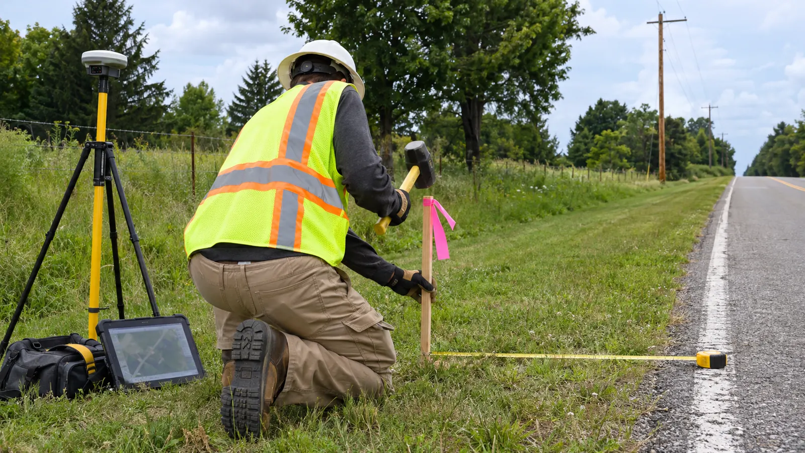
A stake stands between a driveway and a ditch: the pole fits, but its conductor path still needs checking. Shifting the stake away from the driveway introduces a line angle if the neighboring poles stay put. The support for that angle then needs ground space that the original straight alignment never reserved.
That is the placement problem facing utility, co-op and make-ready designers and pole owners. The corridor, the road authority's requirements and the electrical clearances all bear on the same location. We carry that decision into the route drawing and staking sheet so both describe the geometry of the finished line.
Utility pole placement guidelines start with the corridor
Utility pole placement guidelines locate a distribution pole within the available right of way or easement, subject to owner standards, road authority rules and the line's needs. NESC Part 2 governs overhead line safety, including clearances; the acceptable position must satisfy those requirements together rather than follow a universal roadside offset.
The supplied right-of-way boundary gives our designers the corridor's extent; the owner's accepted location criteria establish where its facilities can stand within it. Both pieces of information are needed before choosing the usable alignment. A line drawn just inside the boundary still needs to accommodate the installation it represents, including the parts that project beyond the pole.
Separate mapped boundaries from field features
A survey may show a fence inside the supplied easement edge. Draw and identify each line separately: using the fence as the boundary would change the apparent space available for the route. A disagreement between them goes to the owner for resolution before the disputed position becomes a released stake; our designers label both features so the distinction survives into staking.
Pavement presents a similar trap when a road has been widened inside an older corridor. Mapping that still shows the earlier pavement configuration will give a different offset from the field survey. A common reference system for the boundary and field data lets the designer compare those features directly, without producing a convincing dimension between points that were positioned on different bases.
Crossarms project beyond the pole center, and conductors leave an angle pole in different directions. We check those projections against the corridor limits along with the pole center. On the plan, tracing the crossarm ends and conductor paths exposes a fit problem that a row of pole symbols alone would miss, even with every symbol inside the mapped limits.
Keep the clearance basis attached to the alignment
The IEEE National Electrical Safety Code, IEEE C2-2023, was released on August 1, 2022, with its edition taking effect in February 2023. Publication alone does not establish local adoption. The edition adopted by the governing authority and the owner's applicable requirements give our engineers the basis for calculating clearances under the overhead line safety rules.
A pole shown beside a driveway in plan still leaves a question for the profile: does the conductor clear the crossing under the applicable conditions? Answering that requires the same proposed coordinates in both views, together with the relevant elevations. A displaced survey point is enough to separate the drawing from the calculation, leaving the designer with a valid result for the wrong route geometry.
An existing pole is useful evidence of the route, but a replacement beside it needs its own location review. Changed property access or a road improvement makes the reason especially clear: the old structure occupies a setting that has changed around it. The current project requirements and proposed conductor arrangement guide our engineers as they evaluate the replacement against the changed access or road layout.
A boundary unresolved by the supplied information needs an owner decision before release. Assigning a precise-looking coordinate would hide that uncertainty from the field crew. The staking sheet should distinguish an unresolved proposed point from a surveyed, releasable position, so someone reading the sheet does not have to infer which parts of the alignment still depend on a decision.
Corridor-first layout has a weakness: a tidy row of pole positions looks settled before the supporting structures have been checked. We use the guying and clearance results to decide whether the proposed alignment can be released. Until those checks support it, the route remains provisional, particularly wherever the arrangement depends on ground space the owner has yet to confirm is available.
For the separate question of span spacing, our utility poles guide explains why the interval follows line geometry and loading rather than a fixed placement rule.
| Placement decision | Controlling information | Design consequence |
|---|---|---|
| Roadside position | Owner criteria and road authority accommodation policy | Establish the acceptable roadside location and measurement reference |
| Crossing or driveway position | Surveyed access geometry and overhead clearance basis | Coordinate the support locations with the conductor crossing |
| Guy and anchor space | Line forces and available anchor footprint | Confirm that the support arrangement fits the corridor |
| Movement after staking | Revised coordinates and elevations | Recheck affected spans and release consistent drawings |
Roadway offset follows the accommodation policy
FHWA's Clear Zone and Horizontal Clearance guidance distinguishes horizontal clearance from the roadside recovery area. A curb provides a measurement reference, but the dimension from that curb answers only part of the roadside placement question. We check the owner's dimension separately from the road authority's criteria for a fixed object. The proposed position must satisfy both.
Identify the authority and the reference feature
For federal-aid highways, 23 CFR 645 Subpart B establishes the federal utility accommodation framework, with section 645.209 addressing general requirements. The responsible state DOT's utility accommodation policy supplies the criteria for the particular road and installation. Designers need that policy to select a position; the federal framework supplies no single pole offset transferable unchanged from one highway to another.
An offset measured from the traveled way places a stake differently from the same dimension measured from a shoulder edge. A requirement measured from the right-of-way line introduces another reference altogether. Our staking sheets name and show the required reference feature. That detail matters along irregular pavement edges, where the field crew has several plausible points from which to measure.
FHWA's guidance places aboveground utility facilities as close to the right-of-way line as feasible. Feasibility includes the ground between the road and that line. A ditch occupies space, and a changing roadside slope affects the apparent room for the support arrangement; moving the pole symbol toward the boundary leaves those physical constraints to be resolved with the proposed line geometry.
Review the roadside as it will function
Equal offsets do not make two roadside positions equivalent. The outside of a curve and a straight road segment present different placement questions, even with matching dimensions on the drawing. The road context and accommodation criteria guide our designers along each segment. A repeated offset still needs review before it becomes the alignment for the whole route.
Compare the owner's road improvement drawings with the survey during layout. A proposed drainage adjustment through the current stake would take away ground space that the design relies on. A revised intersection likewise changes the controlling features. Identifying the applicable road drawing and distinguishing proposed edges from surveyed existing edges keeps both conditions visible to the designer.
Averaging incompatible owner and road authority dimensions produces no accepted location. If their criteria leave no common position, the conflict needs a coordinated location decision with the requirements laid out together. The accepted roadside position then returns to the overhead model, where the revised alignment must satisfy the line's clearance requirements before it is ready for release.
Position poles around crossings and driveways
At a crossing, the support locations determine where the conductor traverses the roadway and how the crossing sits within the span. IEEE identifies overhead line clearances within NESC Part 2, Sections 20 through 23. Those clearance rules govern the electrical review; the road authority's criteria govern the roadside fit of the supports.
Evaluate the conductor path between the supports
Moving a support along the corridor while leaving its neighbor fixed shifts a nearby crossing within the span. The road now crosses a different part of the conductor profile. Depending on terrain and support elevations, that part is lower. We recalculate sag and clearance at the crossing's revised location within the span; a check at the pole tops would miss the issue.
Include the road crown and any grade break beneath the conductor in the surveyed profile. Lower ground beside the poles does not represent a higher surface between them, and that higher surface may control clearance. Survey coverage through the crossing gives the calculation the ground it needs to test, rather than leaving the designer to infer the roadway surface from the endpoints.
An oblique crossing extends the conductor path across the roadway compared with a more direct crossing of the same road. Straightening it, however, changes the approach geometry and potentially the adjacent line angles and support requirements. The comparison needs both complete arrangements, judged against owner and road authority criteria, so the designer can check what each crossing does to the adjoining line before choosing one.
Keep the driveway usable
A driveway entrance that looks narrow in an aerial image may flare substantially at the road. The actual flare and the vehicle path identified by the owner, especially for large service vehicles, establish the ground-level space to preserve. We draw that access shape alongside the guy path. Clearing the pole from the entrance achieves little if its support still crosses the usable access.
An uphill driveway illustrates why the access check also needs a profile. The pole stands on level ground beside the entrance, while the surface beneath the span rises toward the property. Moving the pole laterally to open the entrance changes the overhead geometry too; maintaining the applicable clearances requires evaluating the new position against that rise, with different support geometry if needed.
For a make-ready designer, the practical question is whether a new attachment or replacement changes these relationships. Our pole loading analysis connects the proposed geometry to the structural check, so a location accepted for roadway access is also evaluated for the forces imposed by the revised line.
Reserve room for the guy and anchor
An angle pole needs space in the direction its support arrangement requires. USDA RUS Bulletin 1724E-153, Electric Distribution Line Guys and Anchors, approved April 25, 2001, provides guying calculations and assembly guidance. Its mechanics are useful references; the bulletin's historical code references must be reconciled with the project's governing NESC edition and owner criteria.
Draw the anchor before accepting the pole position
Bringing an anchor closer to its pole changes the relationship between horizontal restraint and the force carried by the guy. The empty patch of ground beside a stake therefore needs more examination than whether an anchor fits on it. We calculate the guy forces using the required direction of restraint and the available room, then check whether the proposed anchor position can support that arrangement.
Known buried facilities and the available ground information determine whether the plotted anchor has a workable installation location. An obstruction there reaches back into the alignment decision: preserving the pole position while moving its anchor changes the arrangement being analyzed. Checking that footprint while route alternatives remain open gives the designer a chance to resolve the dependency before releasing either point.
Tracing a guy from its attachment to the anchor often makes a conflict plain. If the path cuts across a driveway or leaves the available corridor, the pole's clear center point has not solved the placement problem. The whole support footprint needs engineering attention before that pole position is released.
Where a down guy cannot fit, owner-accepted span or sidewalk guy arrangements, or an engineered self-supporting pole, may be evaluated as alternatives; our guy wire guide explains the support types.
USDA RUS Bulletin 1724E-150, Unguyed Distribution Poles: Strength Requirements, approved August 14, 2014, provides wood pole strength reference material. Its ANSI O5.1 minimums are the basis for the minimum circumference, diameter and class-load references in our Utility Pole Charts, organized by species, class and length so the reference matches the proposed pole.
Reference dimensions establish the pole being considered; site-specific analysis still needs its proposed attachments and applicable loads. The guy geometry matters just as much as the assembly designation. An anchor turned away from the analyzed direction, or a changed attachment height, describes a different arrangement even if the drawing retains the same nominal assembly label.
A moved stake changes the line calculations
RUS Bulletin 1724E-153, section 1.1, identifies line angles and unbalanced conductor tension as guying considerations. Moving a staked pole calls those inputs back into question at the structure and its neighbors. A small shift on the staking sheet can still change those forces. Enter the revised position in the model to find out what it changes.
Recalculate the connected geometry
Movement along the alignment changes adjoining span lengths, while movement across it introduces or alters line angles. A different ground elevation changes the clearance profile as well. We start with the revised surveyed coordinates and elevation, then trace the calculations that used the earlier position. Those dependencies determine how much of the line needs to be reanalyzed.
At the neighboring pole, the line now approaches from the moved structure's new position. That changes the direction seen by the adjacent support, and the revised spans also warrant review of the line section's tension assumptions. Following those dependencies sets the analysis boundary; stopping at the changed stake would omit part of the system whose geometry has changed.
A conductor shifted toward an existing attachment and a road crossing shifted within a span both need renewed clearance evaluation. Every affected sag and loading case must use the revised conductor path. A check against the old path cannot establish clearance for the new one, even if the roadside position itself has already been accepted.
Show the designer the obstruction that prompted the move along with the proposed position. A pole moved to avoid a buried facility may now have a guy pointing its anchor toward that same facility. Showing the original constraint lets the review follow the conflict across the whole footprint and determine whether the relocation has resolved it.
After the revised checks pass and the owner accepts the location through its process, the staking sheet must match the accepted calculation geometry. That is the release decision for the changed position. The guide to overhead distribution line construction covers field-change records and construction controls that carry the accepted change into the work in the field.
Release decisions for utility pole placement guidelines
Utility and co-op designers: a coordinate is ready for release when the corridor information and overhead model agree, with NESC Part 2 governing the overhead clearance review. An unresolved boundary or roadside reference still needs an owner decision. Keeping that position provisional gives the field crew an explicit instruction about its readiness instead of leaving the uncertainty buried in the design.
Pole owners and make-ready reviewers: use the same proposed position in the loading analysis and staking information. Pole class alone cannot describe the replacement's geometry, particularly at a changed crossing or a constrained guy footprint. The location and support arrangement must work together before our engineers recommend accepting the replacement.
Draftech International delivers turnkey telecom and power infrastructure, with engineering 100% in-house and full turnkey construction delivered by Draftech-managed subcontract crews under Draftech's QA/QC. The people responsible for our work appear in the partner profiles. Active in 24 states. Available across all 50 U.S. states. Route-specific placement discussions start through our free design review or at info@draftech.com.
Our overhead distribution design work covers routing, alignment, guying, sag and clearance checks, and staking sheets. Those checks connect the selected position to the line calculations, while the staking sheets give the field dimensions for that same geometry. For an owner resolving a roadside conflict, the useful result is a position supported by the calculations needed to release it.
Bring the alignment, owner's placement criteria, unresolved locations, surveyed road and driveway features, known anchor constraints and proposed stake moves. These inputs let our designers assess each placement conflict and its effects on the adjoining line.