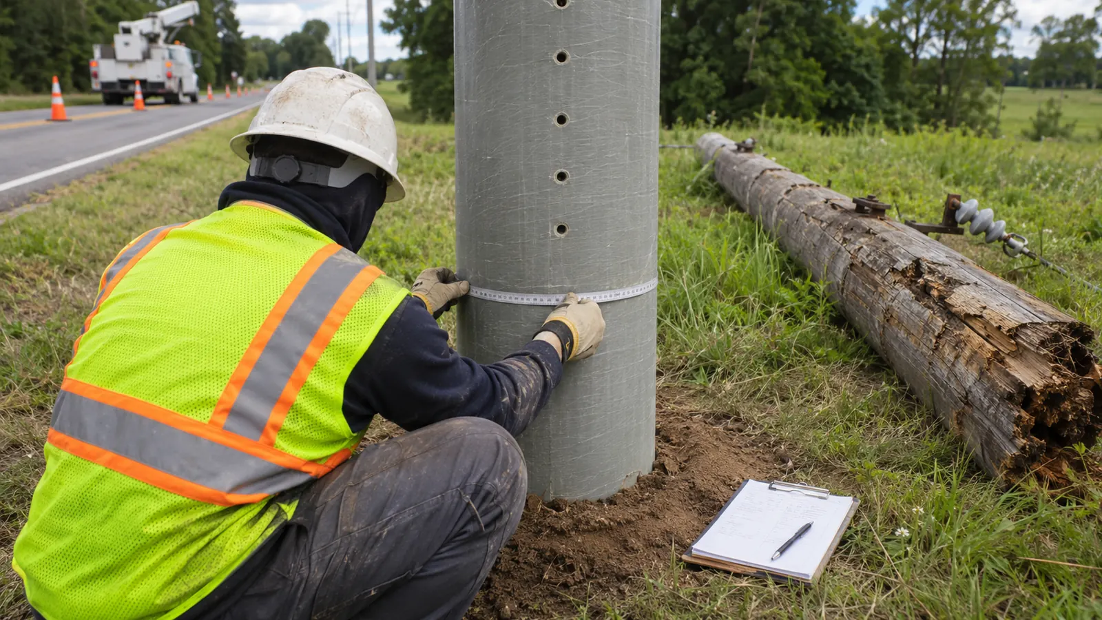
Choosing a composite pole for a difficult distribution site brings a separate set of questions for the attachment designer. Its material label tells us less than the product rating and the owner's construction detail. Those are the records to establish before a proposed cable position becomes a make-ready drawing.
We approach fiberglass poles as specific engineered products. This guide covers how utility, co-op and ISP engineers can review a distribution pole's rating and confirm the attachment conditions that affect the design, from allowable drilling to the grounding path for installed equipment.
What a fiberglass power pole is
A fiberglass power pole is a fiber-reinforced polymer structure that supports distribution conductors or communications cables. Often called a composite utility pole or fiberglass telephone pole, it requires separate checks of strength and deflection. ASCE MOP 104 addresses those comparisons; a wood-equivalent rating requires evidence specific to the product.
Glass fibers reinforce a polymer resin to form the pole's structural wall. The finished member gets its behavior from that combination and its geometry, so an outside diameter cannot tell an engineer how much bending the pole can resist. Capacity comes from the identified product's engineering data. That is what we use for an existing asset or a proposed replacement.
Fiber orientation and wall thickness can differ behind the same smooth exterior, changing the response to an attachment load. Start with the identifier. Tying it to a product record lets us account for those wall properties in the model. Entering an assumed class just to satisfy a software field substitutes a guess for that evidence. An unreadable marking calls for clarification from the owner. A limitation of our product-specific approach is that we cannot complete the capacity review when the owner cannot supply the identified pole's rating data.
Wood, steel, concrete and composites have different structural and maintenance characteristics, outlined in our overview of utility pole materials. A general preference for composites gets us only so far. At the installed location, the particular pole still has to meet the distribution line's requirements, whatever advantages its material offers elsewhere.
Where owners consider composite poles
Low weight makes FRP worth evaluating for rear-lot sets and locations that equipment cannot easily reach. Oak Ridge National Laboratory's Assessment of Commercial Composite Power Pole Performance, ORNL/TM-2021/2068, published May 2021, describes light weight, low conductivity and resistance to rot and corrosion. Those properties explain the interest in wet or corrosive settings, without proving that every product suits every exposure.
How will the pole reach the hole? On a rear-lot replacement, that route and the means of supporting the pole during attachment transfers belong in the engineered installation plan, even when a lighter shaft eases delivery. Modular poles add an assembly question. Compare the instructions with the available work area and show where the crew can carry out the assembly on the replacement drawing.
When storm hardening drives the replacement, we review the connected spans and guying because a stronger pole can redirect load after an adjacent structure or conductor fails. That response depends on the connected system. Include the mounted equipment in the framing review: even a small new communications cable may be attached to a pole where equipment wind area contributes appreciably to the demand.
EPRI's Fire Protection for Poles describes how exposure temperature and duration affect damage and discusses protective treatments for composite poles. Read the exposure conditions closely. The proposed product's fire-test basis and any required barrier details let us assess it against the owner's wildfire-hardening objective. Predicting survival in a particular fire takes evidence about that exposure, beyond the fiberglass designation.
How a fiberglass power pole compares with a wood class
Passing the strength check tells us how the pole resists load. Its deflection may change a clearance or move an attachment beyond the owner's permitted limit. Strength is only part of the comparison. A class label starts 2 checks for us: capacity to resist load and movement under load, both evaluated for the proposed installation even when the label matches the wood pole being replaced.
Read equivalency as a defined comparison
ASCE's Recommended Practice for Fiber-Reinforced Polymer Products for Overhead Utility Line Structures, MOP 104, second edition, published in 2019, treats strength equivalency and serviceability equivalency separately. It is a manual of recommended practice. Its distinction gives us a way to examine the scope of a quoted wood comparison and the conditions assumed in the product documentation. Interchangeability depends on those conditions.
Wood class definitions depend on the wood-pole specification, as explained in our ANSI O5.1 pole specifications guide. For an FRP substitution, retain the product designation and the stated comparison basis in the model record. Replacing that record with only a wood class discards information the next attachment review will need to interpret the capacity correctly.
Where was the reference load applied? Locate that point on the test configuration. Moving a transverse load to another attachment height changes the bending demand; different embedment or exposed length also changes the comparison with the installed pole. Put those dimensions beside the quoted rating and identify whether the product sheet gives an ultimate value or an allowable design value. Otherwise the reviewer has to reconstruct the basis from separate records.
| Review item | What to obtain | Decision it supports |
|---|---|---|
| Strength | Product-specific rating and its load basis | Whether the proposed demand is acceptable |
| Deflection | Stiffness data and owner movement limits | Whether loaded geometry remains acceptable |
| Drilling and hardware | Permitted openings and connection details | How attachment forces enter the wall |
| Climbing | Approved access method and reserved space | Whether the installed arrangement can be serviced |
| Grounding | Owner bonding and grounding detail | How required electrical continuity is maintained |
Check strength through the loaded structure
For the exact pole configuration, the manufacturer's engineering data should describe bending resistance along the shaft and any orientation dependence relevant to the proposed framing. Follow those properties down to the connection region. The bolt group needs its own check: even with adequate shaft capacity, we still have to establish how that particular connection transfers the attachment load through the wall.
An analysis program may lack the identified composite product. Resolve that gap with an approved modeling method whose capacity basis matches the owner's loading cases and design factors. With a convenient catalog substitute, the risk is comparing a factored demand with an unrelated rating. Record how the selected method represents the actual product so the reviewer can check the load and capacity on the same basis.
Check deflection and installed support
Deflection is the loaded pole's movement. Stiffness describes its resistance to that movement. To check the owner's serviceability limits and affected clearances, we compare the predicted displacement using the installed geometry. Exposed length deserves particular attention when a rating comes from a different configuration. A taller installation calls for checking how the added exposed length affects displacement and the clearance being evaluated.
Wet ground can make corrosion resistance attractive while also presenting a difficult foundation condition. Embedment and soil support need their own evaluation, regardless of shaft strength. Both affect the pole's response, which is why we record support conditions separately from exposure. After selecting a material suited to the moisture, evaluate the installed foundation and include its support conditions in the loading record alongside the shaft properties.
Keep the source designation: Put the exact pole product and the rating-document revision beside the model entry. That makes a later catalog substitution visible before someone reuses the result for another attachment.
Confirm drilling, hardware, climbing and grounding
Get the owner's composite-specific construction detail while the attachment height can still change. With the permitted fastening arrangement in hand, we can draw the FRP connection and give the loading reviewer something specific to evaluate. A familiar wood-pole detail may need to change here. Carry any different arrangement into the design, then check the loading result against that position.
Drilling and hardware rules
A hole near an existing opening needs an explicit location on the accepted detail, with the required edge distances shown. Ask the owner which holes are permitted and which product instructions govern field modifications, including treatment of cut surfaces. Dimension the approved position on the drawing. Leaving a generic hole location for the crew to move puts a design decision into the field without the information needed to make it.
Excessive clamping can damage some composite wall arrangements, even when the installed hardware appears secure. For the selected attachment, confirm the approved bearing arrangement and any required sleeve or reinforcement, then specify the applicable tightening procedure. Trace the force through the hardware into the wall as well. Tightening practices familiar from wood-pole work need to give way to the procedure specified for this composite connection.
Survey photographs may show abandoned hardware, existing openings or damage in the proposed attachment area. Identify each condition separately from the new connection so the owner can assess whether it affects continued use of the pole. Choosing a repair requires the owner to assess the condition beyond its visible appearance. Mark the affected location clearly in the field record so the responsible owner can specify an accepted remedy under the applicable product instructions.
Climbing limits and maintenance access
At a rear-lot pole beyond bucket-truck reach, the proposed access method needs review before the attachment layout is settled. Confirm whether the owner permits climbing on the identified product and which equipment or installed steps are required. Wood-pole gaff practices cannot simply transfer to FRP. Plan for the later maintenance visit, too. Position the final cables and enclosures to preserve the approved access arrangement for maintenance as well as the initial attachment work.
A step may sit directly behind an enclosure at the required attachment height. Check the cable route and hardware layout against the owner's climbing-space requirements, including rescue access. Where will workers stand and reach once the attachment is installed? Showing that space on the drawing lets us coordinate any needed relocation with the structural check while the design can still change.
Grounding on a non-conductive pole
Bonding and a deliberate connection to the grounding system may be required for metallic equipment and exposed mounts on a low-conductivity shaft. Ask for the owner's accepted electrical detail and follow the path through the complete equipment arrangement. Account for every required connection, including the metal introduced by the proposed attachment. Verify continuity through the specified connections between those components, rather than relying on the composite wall to provide the electrical path.
Where a grounding conductor runs through or down the pole, check that its route suits the product and remains inspectable at the owner's required access points. During a transfer, a material change can interrupt a required bond if an existing connection is removed without a replacement. Mark retained and replacement connections on the drawing. Following those marks through the transfer detail should let us trace the intended electrical path without guessing what survives the work.
Carry access into the plan: Reserve the owner's required climbing space when positioning communications hardware. Deferring that check until installation can force a connection change after the structural model has already been accepted.
Turn the survey and product data into make-ready
Start the field record with a photograph of the identification marking, then reconcile it with the owner's asset record before choosing a catalog entry. Views of the base and attachment faces let us compare the modeled geometry with what is installed. If the marking and asset record do not resolve the product identity, keep that question open in the design record and identify the owner information needed to answer it.
Build a traceable loading model
Span geometry and attachment heights belong with cable loading inputs in the analysis, as our guide to what a pole loading analysis requires explains. Label each attachment as existing or proposed and pair it with the corresponding field observation in the model record. A diagram that combines both without labels makes the source of added demand harder to review.
When the communications cable designation is uncertain, its visible diameter gives us no reliable basis for assigning weight or tension. Ask the attacher for the applicable data before calculating, and check that the proposed sag condition agrees with the design assumptions. Those cable inputs are needed even when the pole capacity is fully documented. List the unconfirmed properties explicitly; that gives the attacher a specific request to answer and us a record of what holds up the load case.
When a rearrangement moves attachment heights or hardware around the shaft, model the final arrangement explicitly rather than adding a cable to the unchanged survey model. Keep the existing and proposed conditions distinguishable so the reviewer can follow the redistribution of loads. Temporary transfer conditions also need to be flagged for the responsible construction planner, since the loads during that work can differ from those on the completed installation.
An unidentified installed pole is a real limit on this product-specific approach: a precise loading conclusion may have to wait until the owner establishes the rating. State that dependency where the report would otherwise give a capacity result. Entering a nominal wood pole would allow the calculation to proceed, but the result would depend on unverified properties. Keep the unresolved identity visible for the owner and the next attachment reviewer.
Carry the result into the attachment detail
Draftech's pole loading analysis for composite structures models FRP poles from the manufacturer's strength rating and uses the result to design make-ready. For a proposed fiber attachment on an existing composite pole, that connects the capacity calculation to the make-ready design. Bring us the product data together with the owner's attachment requirements. The final arrangement has to satisfy both.
For a relocated attachment, carry the revised position through the drawing, the model and the approved hardware detail. If replacement is required, identify the new product and apply the same review to it rather than calling it only a stronger pole. The installation package should let a reviewer follow either decision back to its structural basis, including the product rating and the arrangement used in the final calculation.
Decide what must be resolved before release
Utility and co-op engineers: Accept a composite pole configuration only after the product rating and the installed support conditions are established. Require the applicable attachment detail in the package. A hardening objective can justify evaluating FRP, but the release decision belongs to the actual structure and its connected distribution spans, with the owner's operating requirements carried into the design.
ISP attachment engineers: Obtain the owner's composite-pole rules before fixing the final cable position. Submit the proposed loading inputs with the requested hardware arrangement, and make unresolved access or bonding details visible in the application. We recommend returning an unidentified pole for owner clarification rather than presenting a completed attachment design whose capacity depends on an assumed material model.
Design reviewers: Follow the proposed change from the survey through the model to the drawing, checking that the product designation stays consistent. A revised bracket or attachment elevation needs its affected checks revisited and its superseded detail clearly distinguished from the current version. Keep the assumptions beside the resulting decision in the review record. Another engineer should be able to check the revision and understand why the arrangement changed without reconstructing the design history.
Draftech International delivers turnkey telecom and power infrastructure, with 100% in-house engineering and full turnkey construction delivered by Draftech-managed subcontract crews under Draftech's QA/QC. Active in 24 states. Available across all 50 U.S. states. For a composite-pole attachment review, use our project contact page to identify the unresolved rating or owner detail, or email info@draftech.com.
A route with unidentified composite poles needs those rating questions answered before its make-ready package is ready for owner review. For qualifying route work, Draftech's free engineering offer covers the first 20,000 linear feet at no cost, from feasibility and field survey through permit approval; the owner reviews each request before Draftech commits the package. Bring the pole records into that review so the proposed scope reflects the engineering the route needs.