IN THIS ARTICLE
A conductor change can leave a distribution drawing looking almost untouched while changing the loads at every support. The replacement still follows the same pole line. Yet its weight and installed tension can force a different structure decision, even when the proposed aluminum area matches the existing conductor.
We start with the circuit requirement and the actual span geometry, then compare the conductor constructions the utility permits under the same loading assumptions and the same required operating duty. This guide explains how to read ACSR designations and decide when steel reinforcement earns its place in an overhead distribution design. Our focus is the route calculation and the package a line contractor can build.
What ACSR Conductor Construction Tells You
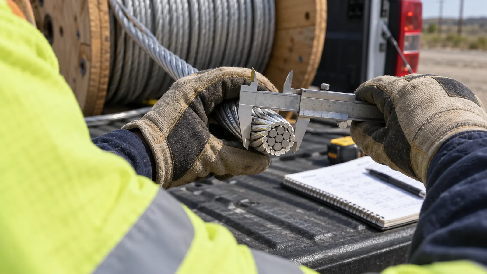
ACSR means aluminum conductor, steel reinforced: aluminum strands surround a coated steel core in the construction covered by ASTM B232/B232M. A 6/1 designation identifies six aluminum strands around one steel strand. Distribution designers consider it when mechanical strength and sag performance must satisfy the route's loading and clearance requirements.
The core changes the mechanical design. The aluminum carries most of the electrical current, while the steel provides reinforcement. Both materials affect the conductor's response to loading and temperature. We need the properties of the complete assembly before calculating support reactions; treating the steel as an unrelated messenger would misrepresent the conductor.
ASTM B232 establishes the material specification
ASTM B232/B232M-24 covers concentric-lay-stranded aluminum conductors with coated steel reinforcement. Its requirements address construction and material properties, including the core wire. It does not approve a particular span. We therefore keep product compliance separate from the route analysis that determines whether the selected construction satisfies the utility's design criteria.
A purchase description should preserve the specified core designation. The suffix matters. If a proposed substitution changes the core coating or strength designation, we require the revised properties before accepting it into the calculation. An unchanged aluminum size does not establish that the substitute has the same mechanical behavior or the same hardware requirements.
Read the conductor and the circuit separately
Bare overhead conductor has no insulation system that makes contact safe. Voltage class belongs to the circuit design and its insulation and clearance requirements. We identify whether the conductor serves a phase or a neutral before evaluating a replacement, because the electrical duty and attachment arrangement differ even where the material designation looks familiar.
The wider electric distribution system establishes the conductor's job. A feeder upgrade may begin with a load forecast, while a lateral replacement may begin with a deteriorated span. Our recommendation must answer that particular problem. Selecting a stronger conductor without resolving the circuit requirement can leave the owner with new material and the original operating constraint.
How to Read ACSR Sizes and Code Words
A code word is a lookup key. ASTM B1006-17(2023), Electrical Overhead Conductor Code Word Names, organizes recognized names by conductor construction and allows suffix modifiers. We carry the full designation into the material schedule. The familiar name helps people communicate, but the approved specification determines what arrives on the reel.
Separate nominal size from strand count
Raven provides a useful reading example: the conventional ACSR designation pairs 1/0 AWG with 6/1 stranding. The first describes nominal aluminum size; the second describes the aluminum and steel strand counts. They answer different questions. A drawing that preserves only the code word leaves the checker to recover information that should already accompany the selection.
Larger sizes are commonly expressed in kcmil, meaning thousands of circular mils. That area designation does not describe the outside diameter of the stranded assembly. We read diameter from the exact conductor data, because the overall envelope matters to fittings and wind loading. Converting an aluminum area into an assumed assembly diameter is an avoidable modeling error.
Strand count also does not state the share of steel by area. Wire diameters matter. Different constructions can use different strand diameters, so counting visible wires is insufficient to establish the mechanical properties. When an existing line lacks reliable records, we request identification evidence before treating the proposed replacement as equivalent to the installed conductor.
Keep the source row with the model
Our preferred handoff includes the approved conductor data beside the calculation input. The reviewer can then check the selected construction without hunting through a generic catalog. We retain the source revision and make any unit conversion visible, so a checker can follow a diameter or resistance value from the approved data into the calculation without guessing. This is especially useful when a material schedule uses customary units while the calculation library stores metric values.
A published rated strength describes the specified conductor under defined conditions; it does not tell a contractor what tension to apply in the field. We keep strength values separate from stringing instructions. The following comparison is a map of design questions, rather than a size table or a set of universal span limits.
| Design question | ACSR | AAC or AAAC alternative | Required decision |
|---|---|---|---|
| Material construction | Aluminum with coated steel core, ASTM B232 | AAC under ASTM B231; AAAC under ASTM B399 | Use the exact approved construction |
| Span and clearance | Steel reinforcement supports mechanical selection | Evaluate the selected aluminum construction's sag response | Calculate the actual span arrangement |
| Weather loading | Weight, diameter and tension affect support loads | Different properties change those loads | Apply adopted NESC and owner criteria |
| Current and temperature | Use construction-specific electrical data | Use each alternative's electrical data | Check the required duty and temperature limit |
| Installation and maintenance | Core designation and compatible fittings matter | Material-specific fittings and procedures still matter | Confirm the utility's approved package |
When Steel Reinforcement Earns Its Place
We favor an ACSR candidate when the route needs its mechanical performance and the full design confirms the benefit. A long open span can justify that evaluation. So can a clearance constraint. We still compare the resulting support loads with the capacity of the structures that will carry them, rather than stopping at conductor strength.
AAC and AAAC are different alternatives
AAC is all-aluminum conductor, with aluminum 1350 construction covered by ASTM B231/B231M. AAAC uses aluminum alloy conductor covered by ASTM B399/B399M. Neither has the conventional ACSR steel core. We keep the distinction explicit in the comparison: replacing the words "all aluminum" with a single generic material record would erase the alloy difference that the engineer needs to evaluate.
For a short span with adequate clearance, an approved AAC construction may satisfy the job without steel reinforcement. AAAC deserves its own calculation where the utility accepts an alloy alternative. Compare complete designs. An equal-area comparison alone can obscure differences in resistance or mechanical response, and an equal-diameter comparison answers a different question again.
Corrosion exposure deserves attention before standardizing a material across the route. We review the owner's approved conductor and fitting requirements for that environment rather than treating a bare material name as a durability guarantee. Core protection remains relevant for ACSR. The connection details still matter for all-aluminum alternatives, so removing steel does not remove the need for an installation specification.
Substitution check: Ask for the exact proposed construction before accepting "equivalent conductor" on a submittal. Our check starts with the changed properties and follows them through the route calculation; a matching code word alone cannot close that review.
A real limitation of choosing ACSR for its strength is that the surrounding pole line may need changes to accommodate the selected tension. We assess those changes before endorsing the conductor, including whether the existing supports can carry the calculated reactions without a replacement program that the owner has yet to authorize. Otherwise, a choice intended to simplify a crossing can create unresolved loading at a dead-end or leave the existing guy arrangement outside the approved design.
When the material decision and support design need one accountable package, our electric utility engineering for distribution routes connects them. We define what must be verified in the field before issuing the calculation. That keeps an uncertain attachment height from quietly becoming a precise-looking clearance result.
Check Span Length, NESC Loading and Sag-Tension Together
There is no universal maximum span. The allowable arrangement depends on conductor properties and installed geometry under the applicable load cases. USDA RUS Bulletin 1724E-152, The Mechanics of Overhead Distribution Line Conductors, explains sag-tension relationships and ruling-span methods. We use that engineering framework with the project's adopted criteria, rather than extracting a span limit from the conductor name.
Span geometry comes before the result
The level-span parabolic approximation expresses sag as wL^2/(8H), where w is weight per unit length, L is span length and H is horizontal tension, using consistent units. It shows why span length matters strongly. It is only an approximation. Our final design must account for the actual geometry and the conductor's changing condition.
A ruling span represents a tension section for sag-tension work; it is not simply the longest span or an arithmetic average. Unequal spans require care. For the design package, we want the section boundaries identified on the plan and the individual spans traceable to field measurements, so the person checking clearance can reproduce the arrangement that the calculation assumes.
Attachment elevations deserve the same attention as horizontal distance. A sloping span can place its low point away from the midpoint, and a crossing surface can change elevation beneath it. We check the clearance location on the profile using the attachment elevations and the surface beneath the span, so the reported separation refers to the actual point that controls the design. A midpoint label is insufficient when the controlling separation occurs elsewhere along the conductor.
Loading criteria and clearance cases have different jobs
The NESC is IEEE C2; the applicable edition and the utility's additional requirements belong in the design basis. The 2023 edition includes Rule 250 loading provisions and separate clearance requirements. We establish which cases apply to the particular line. A loading-district label alone leaves too much unresolved to serve as the complete criteria statement.
Ice and wind can change the conductor loading, while temperature changes its length and tension. Each calculation needs the appropriate condition. Our review of the NESC loading district map explains why the map is an input to the engineering work. The designer still needs the applicable rule checks and the owner's requirements for the route.
We ask the checker to distinguish the condition controlling support loading from the condition controlling clearance. They can differ. A pole may satisfy the required structural case while the conductor lacks sufficient clearance at its governing sag condition, so an acceptable pole result cannot stand in for the clearance calculation.
Keep the cases identifiable: Put the governing condition beside each reported result. A clearance value and a support load become difficult to review when the package hides which temperature or weather case produced either number.
Initial and final conductor conditions also require explicit treatment. Creep and load history affect the sag-tension relationship, so a newly installed condition does not describe every later condition. RUS Bulletin 1724E-152 addresses this distinction. We require the design output to identify the condition used, then align the construction instructions with the approved installation assumptions.
Carry the Selection Through Rating and Installation
A catalog current value needs its assumptions. IEEE 738-2023 provides a method relating bare overhead conductor current and temperature under defined weather conditions. It does not select the utility's rating assumptions. We document those assumptions before comparing alternatives, and we check whether the associated conductor temperature remains consistent with the clearance analysis.
Check the circuit duty before increasing size
The circuit can be limited by something other than conductor heating. Voltage drop may drive the selection, or an upstream device may constrain the usable capacity. We review the required operating duty before recommending a larger conductor, because adding aluminum to the span does not resolve an operating constraint located elsewhere in the circuit or its equipment. The broader distribution line modeling work connects the proposed material to the electrical behavior of the circuit.
An ampacity comparison should use compatible assumptions for every candidate. Keep the temperature basis visible. If one alternative is evaluated under different weather or operating assumptions, the comparison no longer isolates the effect of conductor selection. We ask for that difference to be resolved or explained before using the result to support a purchase.
Existing equipment also needs a compatibility check. A proposed conductor may require different connectors or dead-end assemblies even where its nominal size seems familiar. We expect the material schedule to identify approved hardware for the exact construction. That gives procurement a usable requirement and gives the contractor a defined basis for raising a substitution request.
Issue instructions the line contractor can use
Stringing information must identify the intended section and conductor condition. The crew needs the approved relationship between temperature and sag or tension, with the measurement method established in the construction requirements. We do not substitute rated breaking strength for that instruction. The responsible engineer must resolve a field condition that falls outside the issued design.
Changed pole locations require review. If a structure moves during construction, we expect the contractor to report the revised geometry before using the original stringing information for the changed section. Our partner-led engineering delivery keeps the design responsibility clear. A field adjustment needs an engineering disposition that can be carried into the final record.
Closeout should identify the installed conductor against the approved material record. The owner's maintenance team will need that identity when a future repair reaches the same span. We also want accepted field changes reflected in the record drawing, because a correct original calculation becomes difficult to use when the installed attachment no longer matches it.
Choose the Conductor the Whole Route Can Support
Utility distribution engineers: Select ACSR when the evaluated construction resolves the mechanical requirement and the completed circuit checks support it. Require an explicit comparison with an approved all-aluminum alternative where either can meet the duty. The recommendation should identify what controls the choice, so the next reviewer can distinguish a route requirement from a customary material preference.
Electric cooperatives: Keep an approved standard conductor where it meets the calculated requirement and fits the maintenance program. Request an exception for a documented constraint. A new material family should earn its place through the route analysis, with procurement and operations able to support the resulting conductor and hardware combination after construction ends.
Line contractors: Build from the released conductor schedule and section-specific stringing information. Raise discrepancies before installation. A reel designation that differs from the approved submittal needs a written resolution, and a shifted support needs review of the affected geometry. The design package should tell the crew which document governs when an old field sketch conflicts with the current issue.
Draftech's engineering is 100% in-house. Our power scope includes substations, electric distribution and make-ready; full turnkey construction is delivered by Draftech-managed subcontract crews. Active in 24 states. Available across all 50 U.S. states. Use our project contact page or info@draftech.com to discuss a route whose conductor selection and field geometry need to be resolved together.
For a qualifying route, the Draftech free-design offer covers engineering of the first 20,000 linear feet at no cost, from feasibility and field survey through permit approval. The owner reviews each request before Draftech commits the package. That review starts the conversation about turning the unresolved span and clearance questions into a defined engineering scope.