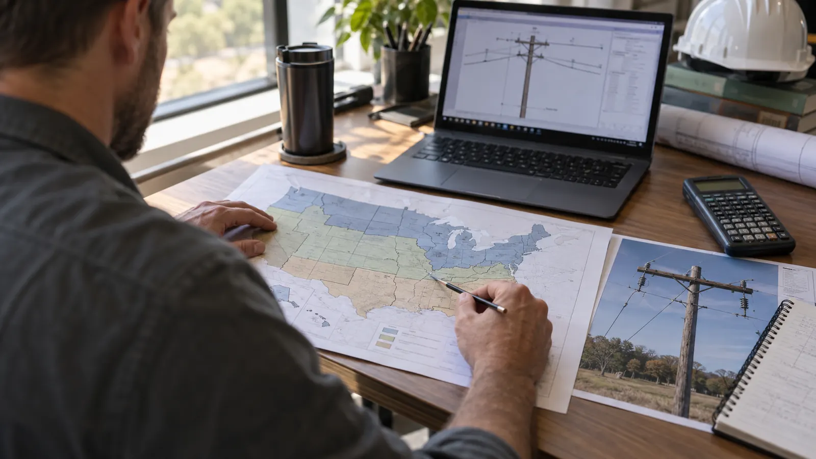
A loading-district selection can look like a small software setting until it changes the pole replacement scope. We want that choice resolved before an aerial fiber design reaches attachment review. A district label establishes a weather assumption; the engineer still has to determine which other loading cases apply to the actual structure.
This guide explains how we read the district map and carry its assumptions into pole loading. It also separates the extreme-weather maps from district loading so a project manager can ask useful questions about a calculation report without treating a map screenshot as an attachment approval.
What the NESC loading district map defines
The NESC loading district map assigns geographic areas to 3 general loading districts: heavy, medium and light, with separate warm-island provisions. Under Rule 250B, the assigned district determines combined ice and wind assumptions for overhead-line structural calculations. Engineers use the mapped location with the code's loading table, then evaluate other applicable weather cases.
The reference is IEEE C2-2023, the 2023 National Electrical Safety Code, published August 1, 2022. IEEE identifies it as the active edition. We confirm the edition adopted for the project and the pole owner's criteria before selecting software load cases, because a current publication and a jurisdiction's adopted requirements can differ. The owner's attachment standards may also impose additional loading checks.
District boundaries belong to the map
Figure 250-1 assigns the areas; a list of states cannot substitute for locating the pole on that figure. We use the structure's coordinates and inspect the boundary at a usable scale. If a route approaches a district boundary, we resolve the affected poles individually rather than extending the first pole's setting through the entire job. The boundary deserves a recorded decision.
The NESC classifies these districts by the relative simultaneous occurrence of wind and ice accumulation on wires. Those labels describe prescribed combinations, not a ranking of every possible storm. Heavy loading includes more assumed radial ice than medium loading, while light loading uses a higher district wind pressure without ice. A light-district selection therefore gives no basis for skipping a separate extreme-wind check.
Loading maps and clearance zones serve different checks
Structural loading asks whether the line components can withstand the prescribed forces. Clearance calculations ask whether conductors remain sufficiently separated from other facilities and accessible surfaces under the applicable conditions. The NESC addresses ice and wind for clearances separately in Rule 230B. We keep the clearance basis visible beside the structural basis so similarly named zones do not conceal a mismatch between calculations.
An attachment can pass the pole-strength calculation and still need a height change to satisfy clearance. Conversely, moving an attachment to gain separation changes its moment arm and can alter pole demand. Our guide to NESC compliance for fiber attachments explains how those checks fit the attachment package. We rerun the affected model when the proposed arrangement changes.
Reading the NESC loading district map into design inputs
The district selection supplies a set of conditions, not a finished force at the groundline. Table 250-1 connects each district with prescribed conditions. These include radial ice thickness and horizontal wind pressure. Temperature enters the conductor tension calculation. The table below summarizes the district conditions; engineers must also apply the code's conductor-loading provisions and the appropriate strength rules when building the full model.
We retain the unit labels. They belong in the design basis. Radial ice thickness is measured outward from the cable surface, while wind pressure acts on projected area. Neither value is the percentage of pole capacity being used. That distinction matters when a project manager compares reports: the same district can produce very different utilization on poles with different attachments or span geometry.
A loading report should make its assumptions readable before presenting a passing percentage. We want the district assignment tied to a pole identifier and the software case tied to the governing code edition. An imported model can preserve an earlier setting even when its filename has changed. Reviewing the input record takes less interpretation than trying to infer the weather basis from the final reactions.
| Rule 250B condition | Radial ice | Horizontal wind pressure | Temperature |
|---|---|---|---|
| Heavy | 0.50 inch | 4 lb/ft² | 0°F |
| Medium | 0.25 inch | 4 lb/ft² | 15°F |
| Light | 0 inches | 9 lb/ft² | 30°F |
| Warm islands, sea level through 9,000 feet | 0 inches | 9 lb/ft² | 50°F |
| Warm islands, above 9,000 feet | 0.25 inch | 4 lb/ft² | 15°F |
Heavy loading: ice changes weight and wind area
Heavy-district calculations include ice weight and wind acting on the enlarged cable profile. The load does not increase only because the cable weighs more. Ice also increases the area exposed to wind, and the loaded conductor tension affects the forces transferred into the support. We check the installed cable arrangement rather than treating the new fiber's bare weight as the entire added demand.
Medium loading: smaller ice thickness still changes tension
Medium loading uses less radial ice than heavy loading, but that does not make the resulting pole utilization a fixed fraction of the heavy-district result. Geometry remains decisive. At an angle pole, conductor tension creates a resultant load that depends on the line direction, and unequal spans can further change the force balance. We evaluate the actual span arrangement first. Then we recommend a guy or replacement.
Light loading: the wind pressure is higher
Light loading assumes no ice in its district case. Its higher wind pressure can make exposed area important, especially when an attachment adds a cable bundle or equipment surface. We separate the weight of each proposed attachment from its wind area in the model. A cable with a small weight contribution can still increase transverse loading enough to matter on a pole with limited remaining capacity.
Warm islands: elevation changes the prescribed case
The warm-island provisions cover islands between 25 degrees south and 25 degrees north latitude. The elevation distinction in Table 250-1 matters because mild conditions near sea level do not establish the weather assumptions at higher elevations. We record site elevation when applying this provision and keep it distinct from attachment height above ground. Those measurements answer different engineering questions.
Resolve a district-boundary question with the pole owner before applying one loading template to a route. Keep the accepted boundary interpretation with the design basis so the next model revision uses the same location decision.
Extreme wind and ice maps are separate load cases
Rule 250C addresses extreme wind without ice; Rule 250D addresses extreme ice with concurrent wind. We evaluate each required case separately. Combining the largest wind value from one map with the largest ice value from another would create a different weather case from the combination the code prescribes, unless an additional owner criterion explicitly requires that combination.
Rule 250C: select the wind map for the construction grade
IEEE's Errata to the 2023 Edition National Electrical Safety Code, Correction Sheet #1, issued November 15, 2023, corrects Rule 250C and portions of Figure 250-2(a). The corrected rule identifies a Grade B map with a 100-year mean recurrence interval and a Grade C map with a 50-year interval. We select the applicable construction grade first. Then we read the wind value.
The mapped speed represents a 3-second gust at the stated reference height and exposure. The calculation then accounts for exposure and gust response, with force coefficients applied to projected areas. Wind load varies with speed squared. A map value therefore cannot be entered as though it were a district pressure, and the construction grade cannot be selected merely to obtain the lower wind speed.
Special wind regions need attention. We examine the map notes and the site's terrain before accepting a default value, because local wind behavior can differ from the broad contour pattern. A route crossing exposed terrain deserves that review even if the district selection stays constant. The resulting assumptions should be visible in the calculation package, where the pole owner's reviewer can evaluate them.
Rule 250D: keep extreme ice and concurrent wind together
The extreme-ice maps establish ice loading with its associated concurrent wind conditions. These inputs describe the same design event. We retain the applicable temperature basis when calculating the loaded conductor response, then compare the resulting component demands with the other required cases. A map showing greater ice thickness does not establish the governing pole result by itself; the associated wind and tension calculations still matter.
Rule 250D can change which part of the system controls. Added ice increases vertical demand, while the cable's loaded tension may change the forces on a dead end or guyed structure. We inspect the component results instead of relying only on the headline pole utilization. A satisfactory pole result leaves a separate question about whether the guy system and its anchorage can carry their assigned loads.
The height trigger needs the actual rule text
The corrected Rule 250C applies when a structure or its supported facilities exceeds 60 feet above ground or water, and it also identifies applicability through specified Rule 261 provisions. We check Rule 250D's own applicability language separately. A short-pole assumption must account for the supported facilities and the owner's requirements, not just the nominal length stamped on a wood pole.
We also distinguish a required code case from an owner-specified reliability case in the report. Both can affect acceptance. Clear labeling lets the reviewer see why a case was run and prevents a later scope discussion from turning into an argument over whether the engineer chose an arbitrary storm. The project's accepted criteria should settle that question before model production starts.
How engineers turn weather inputs into pole loading
The pole model begins with field information. We need enough geometry to place the loads where they act and enough material information to establish capacity. A district designation cannot correct an incorrect attachment height. For the field side of that work, our pole-loading measurement guide explains the inputs that need to reach the analyst.
Match the model to the proposed attachment
We model the existing arrangement first. Then we evaluate the proposed one. Cable diameter affects wind area, and the span configuration affects how conductor loads reach the structure. The analyst must also account for the support conditions that resist those forces. A guy shown in a photograph needs usable geometry and a capacity basis before it can be treated as adequate support for the proposed load.
A useful report preserves the difference between existing demand and proposed demand. Otherwise, a reviewer cannot tell whether the new attachment causes an overload or whether the submitted model already shows a problem before the addition. We ask for that distinction early. It shapes the make-ready discussion and the owner's decision about which work must precede attachment approval.
The strength comparison must use the applicable load and strength factors for the construction grade and material. We compare factored demand with the permitted capacity for each component, then identify the controlling case. Comparing raw wind pressures alone would miss those factors. A pole that passes district loading still needs the remaining required cases checked before the analyst can report an acceptable proposed configuration.
Our pole loading analysis connects the verified field geometry with the accepted weather criteria and the proposed attachment configuration. Engineering remains 100% in-house at Draftech International. We carry the calculation outcome into the make-ready drawings so a replacement recommendation or attachment adjustment has a defined engineering basis rather than becoming an unexplained note on a plan sheet.
Check the selected load-case contents after a software or catalog update. A familiar case name can conceal an older wind map or a different construction grade, and the printed report needs to show the assumptions used in this revision.
Use a screening result within its limits
The Pole Loading Calculator is a free screening pre-check of one tangent wood pole for NESC Rule 250B wind and ice load against its capacity by class and district. It is not a stamped pole loading analysis. We use that distinction to set expectations before anyone treats a screening result as evidence that a pole owner will approve an attachment.
Screening is useful for an early question about whether the chosen assumptions warrant closer review. It cannot establish that the surveyed configuration matches the model or that all required extreme-weather cases have been evaluated. Our own simplified checks have that limitation too. We would rather identify an unresolved input than present a precise utilization figure whose apparent certainty comes from a default setting.
Next steps for the route owner and attachment applicant
For a pole owner: establish the accepted loading criteria before reviewing a batch of attachment applications. Require the report to identify the code edition and the reason for each weather case. That makes differences between submissions reviewable and helps distinguish a genuine capacity problem from inconsistent assumptions across consultants. Keep the district-boundary interpretation available to the people maintaining the model library.
For an ISP project manager: obtain the loading basis before using replacement counts to set a construction budget. Ask whether the proposed arrangement has been checked against every applicable case and whether the report distinguishes existing deficiencies from the new attachment's effect. If field data remains uncertain, make that uncertainty visible in the schedule instead of treating the current replacement count as final.
For the design engineer: preserve enough of the input record to reproduce the result after an attachment height changes. We expect the revised drawings and calculation report to describe the same arrangement. Reusing a previously accepted map selection is reasonable only when its location and governing criteria still apply; a changed route or owner standard can require a fresh review.
Draftech International provides turnkey telecom and power infrastructure, with in-house engineering and full turnkey construction delivered by Draftech-managed subcontract crews. Our partner and company overview explains the team behind that work. Active in 24 states. Available across all 50 U.S. states. A route can move from field survey through closeout under one accountable team, while the loading calculations remain tied to the pole owner's acceptance process.
When uncertain district assignments or incomplete field geometry are holding up a route, we connect the survey findings to the loading analysis and make-ready package before construction is committed. Send the route's current design basis to info@draftech.com so we can discuss which unresolved inputs are affecting the attachment scope and what needs to reach the pole owner next.
For an eligible route still at the feasibility stage, our free design offer provides a way to establish that engineering basis: Draftech engineers the first 20,000 linear feet of a qualifying route at no cost, from feasibility and field survey through permit approval. The owner reviews each request before Draftech commits the package.