Overlashing fiber optic cable on existing strand is one of those techniques that looks straightforward until you're 40 poles into a route and the load calc flags a problem. The concept is simple — wrap new lashing wire around an existing messenger and its attached cables to add another cable without installing new strand. In practice, it requires real engineering discipline: you're relying on someone else's infrastructure to support your cable, and if that infrastructure is already loaded close to its limit, you've got a compliance problem before you even start pulling fiber.
Structural integrity starts before construction. Draftech's pole loading analysis service covers O-Calc Pro and SPIDAcalc analysis, NESC compliance, and joint use applications for fiber attachments across 22 states.
This covers what you need to know from an engineering and field standpoint, including the numbers that actually matter.
Overlashing vs. New Strand Installation — When Does Each Make Sense?
The choice comes down to the condition and capacity of the existing messenger, your make-ready situation, and the long-term stability of that aerial plant.
Overlashing makes sense when: the existing messenger has confirmed spare capacity, the host attacher is an established, stable entity unlikely to remove their strand in the next decade, the pole loading analysis clears, and the alternative would require a new joint use application with associated make-ready engineering and fees. On a 6-mile rural route where the cable TV company has had their 3/8" EHS strand up for 15 years with one or two lashed cables, overlashing a new 144-count ADSS-style fiber is often the right call. The make-ready cost savings alone — at $800 to $2,500 per pole depending on market — can be substantial on a 200+ pole route.
Dedicated new strand makes more sense when: the existing messenger is aging or shows corrosion, the host entity is a competitor with reasons to eventually remove their plant, the route has high-value fiber requiring independent maintenance access, or the existing strand is already carrying two cables and a third would push it close to capacity limits. A strand mapping and aerial plant assessment done before design will usually surface these issues. Don't assume the existing strand is healthy because it's still up — some of it has been up for 30 years and looks fine from the road.
The Physics: Messenger Capacity and What the Numbers Actually Mean
Every overlash design starts with the same question: can the existing messenger handle the added weight?
The two most common messenger sizes in aerial telecom plant are 1/4-inch EHS (Extra High Strength) and 3/8-inch EHS. Their rated breaking strengths differ substantially:
- 1/4" EHS: Rated breaking strength approximately 6,600 lb. Working load (using a 2.5x safety factor per NESC requirements) maxes out around 2,640 lb total distributed load. (see our OSHA safety requirements guide)
- 3/8" EHS: Rated breaking strength approximately 14,400 lb. Working load up to around 5,760 lb total — significantly more headroom for additional cables.
But rated breaking strength isn't the number you design to. What matters is the remaining capacity after accounting for the messenger's own weight, existing lashed cables, hardware, and the ice and wind loads required by your NESC loading district. In NESC Heavy Loading zones (roughly the northern tier of the U.S.), you're designing for 0.5-inch radial ice combined with wind — and that loading can triple the effective weight per foot compared to a bare cable in calm conditions.
Common fiber optic cable weights for typical aerial-lashed products run:
- 12-count to 24-count tight buffer or loose tube: 0.06–0.09 lb/ft
- 48-count to 72-count: 0.10–0.16 lb/ft
- 96-count to 144-count: 0.17–0.28 lb/ft
- 288-count or larger: 0.35–0.55 lb/ft depending on construction
Corning's installation guides for their SMF-28 Ultra product family and Prysmian's aerial fiber specs both document these values — always verify against the specific product datasheet since construction varies. Don't design from memory on cable weights.
Add ice loading at 0.5 inches of radial ice (adds roughly 1.24 lb/ft per inch of overall cable diameter), then check the result against available messenger capacity. That's the engineering check. It's not optional, and on poles where the existing strand is already hosting copper and coax along with a fiber cable, you may have very little room. We've run routes where the load calc came back with 3% remaining capacity on the 1/4" EHS messenger — technically it cleared, but we recommended upgrading to 3/8" on that segment rather than leaving that kind of margin on a route through a Pennsylvania ice zone.
Span Length and Sag: The Numbers That Drive Clearance
Overlashing doesn't just affect load. It changes the sag profile of the entire bundle.
Adding cable weight to an existing messenger increases sag. Increased sag means reduced ground clearance at midspan. On standard 125-foot spans, the additional sag from a 144-count fiber (0.22 lb/ft) on a 3/8" EHS messenger typically runs 3–6 inches depending on initial tension and temperature conditions. That sounds small. But if the existing bundle is already at minimum NESC clearance — 18.5 feet over roadways, 15.5 feet over driveways, 11.5 feet in other areas — those extra inches matter.
Span length is the bigger variable. The ruling span for the section drives sag calculations, and spans over 150 feet amplify the sag impact of added weight considerably. On a route outside Baton Rouge a few years back, we had a section with spans averaging 178 feet — well above the typical 125-foot assumed in standard overlash checks. When we ran the actual ruling span sag calculation with the added cable weight, three spans failed minimum roadway clearance by 7 to 11 inches. Those poles needed make-ready adjustment before overlashing could proceed. Wouldn't have caught it without doing the math properly.
Clearance check standard: Always calculate post-overlash sag at maximum operating temperature (typically 167°F / 75°C for fiber) plus maximum ice load condition for your NESC district. Both conditions must independently meet clearance minimums. Neither alone is sufficient.
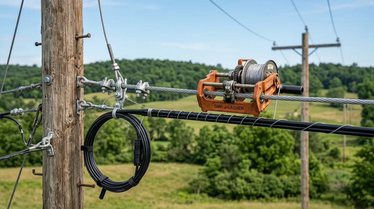
The J-Lasher: How the Field Work Actually Goes
The J-lasher is the machine that does the work. It's a motorized device that rides along the messenger/cable bundle, spinning lashing wire in a continuous helix as it travels. Standard lashing wire for telecom applications is 0.045-inch galvanized steel or stainless — 0.045" is the most common, with a break strength around 400 lb, which is more than adequate for securing cable to strand.
For overlashing, the J-lasher captures the entire existing bundle — messenger, existing lash wire(s), existing cable(s), and the new cable being added — and applies new lashing wire around all of it simultaneously. The new cable rides in a cradle or guide on the lasher as it moves down the span.
Crew Requirements and Lashing Speed
Overlashing is typically a 2-person operation. One person drives the bucket or works the winch on the lashing machine. The second manages the new cable, watches for obstructions, and handles the end work at each pole. A well-run crew with unobstructed spans can lash 600 to 900 feet per hour. Congested poles, frequent crossings, and tight work areas slow that down to 200–400 feet per hour. On an urban route with pole spacing at 80 to 100 feet and lots of existing hardware, budget your crew time conservatively.
Lashing speed also varies by cable diameter. Larger cables require more tension management as the lasher advances — you can't just run it at maximum speed on a 288-count cable through a series of sharp bends.
Minimum Bend Radius During Lashing
This one gets field crews in trouble more often than it should. Fiber optic cables have a minimum bend radius that must be maintained both during installation (dynamic bend radius) and permanently (static). For typical loose-tube aerial cables, the dynamic bend radius during installation is usually 20× the cable outside diameter; the static (permanent) radius is typically 10× OD.
During lashing, the biggest risk is at the poles where the cable transitions around the lashing ring and forms an expansion loop. If the crew is moving fast and not watching cable management, the cable can fold back on itself at angles that create permanent microbends — the kind you won't see until you do an OTDR trace and find unexpected loss at every pole location. Corning specifically calls out the need for controlled feeding tension and proper loop formation at attachment points in their field installation guides.
On 12-count through 48-count cables with OD around 0.47–0.55 inches, the minimum static bend radius runs 4.7–5.5 inches. For larger 144-count and 288-count cables with OD around 0.75–0.90 inches, minimum static bend radius is 7.5–9.0 inches. Verify against the specific cable spec sheet — these vary by manufacturer and construction type.
Pole Hardware: Expansion Loops, Drip Loops, and Lashing Rings
At every pole, the overlashed cable needs proper termination hardware. This isn't optional and it's not just cosmetic — it's structural and protective.
Expansion Loops
Temperature cycles cause cable to expand and contract. Over a span of 125 feet, a 0.8-inch OD cable will move roughly 0.6–0.8 inches across a 100°F temperature swing. That doesn't sound like much until you multiply it across 50 spans and realize the accumulated tension stress at the end of each run. Expansion loops — a figure-eight or D-loop of cable secured to the strand with a lashing ring at each pole — provide the slack that absorbs this movement without pulling the cable tight at the termination points.
Loop size matters. Too small and you defeat the purpose. Too large and it sags below clearance requirements or catches debris. A 24–36 inch loop diameter is typical for cables in the 0.5–0.9 inch OD range on standard spans. On long spans or in areas with extreme temperature cycles — the upper Midwest or high-altitude Western routes — size up.
Drip Loops and Moisture Management
Any cable entering a structure or transitioning from aerial to conduit needs a drip loop — a low point that prevents water from tracking along the cable sheath into the enclosure. Standard practice is a minimum 12-inch drop below the entry point before the cable rises back up to the entry. On aerial-to-riser transitions at poles, the drip loop goes just above the riser conduit entrance. Miss this on a BEAD-funded build and you'll be correcting it during the as-built walk — at your cost.
Bug Nuts and Hardware at Crossings
Where the overlashed bundle crosses other aerial facilities — power secondaries, parallel communication runs — you need to maintain NESC crossing clearances. The problem field crews run into is that the additional sag from the new cable, combined with sag from temperature, can put the bundle closer to crossing facilities than the pre-overlash condition. Survey crossings explicitly during design. Don't assume clearance will be fine just because the existing bundle clears — it changed when you added weight.
Bug nuts — those small, pre-insulated lugs used to secure lashing wire ends at poles — get missed more than you'd think. A loose lashing wire end left without a bug nut will eventually work loose, creating a hanging wire that can catch vehicles or other cables. Check every pole termination. On a 300-pole route, that means 600 checks minimum — and it's worth it.
Tension Management During Installation
Overlashing requires managing three things simultaneously: the tension on the new cable being fed from the reel, the mechanical behavior of the J-lasher as it advances, and the condition of the existing bundle as additional weight is applied progressively along the span.
Feeding tension on the new cable should typically be held at 20–60 lb depending on cable size and span — high enough to prevent it from sagging below the existing bundle before the lasher captures it, low enough to avoid overstressing the cable jacket or inducing excess tension at the lashing rings. Prysmian's installation guidelines recommend a maximum installation tension of 600 lb for their LXE series distribution cables in aerial applications; for overlashing specifically, you'll never approach that limit with proper technique, but tension spikes during reel changes or at obstacles can briefly exceed 200 lb if the crew isn't managing it.
When the existing strand already carries a coax cable plus a copper pair — common on older rural telephone company plant — the combined bundle diameter can reach 2.5–3.5 inches. Running a J-lasher over a bundle that large creates more resistance and requires slower travel speed. Budget extra time on these routes. Forcing the lasher through too quickly on a large bundle leads to irregular lash pitch, which creates localized stress points on the cables being secured.
Dual lashing: On spans over 175 feet or on cables over 0.75 inches OD, many engineers specify dual lashing — two separate passes of lashing wire at offset pitch. This distributes the clamping force more evenly and reduces the chance of the new cable shifting laterally on the bundle in high-wind events. It adds about 35% to lashing material cost but is worth it on exposed routes.
The Load Calculation You Can't Skip
Every overlash design needs a formal pole loading analysis with O-Calc Pro or equivalent software. Not a back-of-envelope check. Not "we did a similar route last year and it was fine." A real model with the actual cable weights, actual span data, actual pole class and height, and actual attachment heights for every pole in the route.
O-Calc's loading module can be finicky when you have multiple cables at similar attachment heights — the software needs clean attachment data to differentiate the existing bundle from the new addition. We've had to go back to field survey crews to re-verify attachment heights on poles where the initial input was ambiguous, because a 6-inch difference in attachment height changes the moment arm calculation enough to matter on borderline poles. Don't shortcut the input data.
The full NESC pole loading compliance check needs to confirm: vertical load capacity at the attachment point, transverse load under wind and ice, ground clearance under maximum sag conditions, and adequate climbing space for future access. On poles where the existing bundle already sits at 15 feet above ground in a 15.5-foot minimum clearance zone, adding sag from overlashing may actually require raising the entire attachment — which puts you back into make-ready engineering territory.
For a complete comparison of when aerial plant (including overlashing scenarios) makes more economic sense than underground construction, our breakdown of aerial vs underground fiber cost comparison covers the decision factors in detail.
Common Field Problems We Actually See
Tangled lash wire is the most common crew frustration. The lash wire reel needs to unwind freely as the lasher advances — if the reel binds or the wire kinks, the lasher stalls or applies uneven pitch. Set up the reel on a proper stand with controlled tension, not loose on the bucket truck floor. Simple fix. Crews that learn this the hard way waste a lot of time re-running sections.
Clearance violations at crossings, especially road crossings, show up during post-construction walk-downs more than they should. The problem is usually that the field crew checked clearance on a mild-temperature day with no ice loading, and the actual minimum clearance condition — maximum sag at high temperature plus ice — was never physically verified. This is a design responsibility before crew ever gets there, but it's a common field surprise on routes where the engineering was rushed.
Missing expansion loops. Some crews, especially crews more experienced with coax lashing than fiber, skip or undersize expansion loops because they didn't cause obvious problems on coax plant. Fiber is less forgiving. A tight terminus with no expansion accommodation can micro-crack the glass under thermal cycling, showing up as elevated attenuation 6–18 months after installation. By then the crew is long gone and the root cause is hard to identify without a detailed OTDR trace and physical inspection at each suspect pole location.
Inadequate coordination with the host strand owner. The entity whose strand you're overlashing is a party to the joint use agreement, and they need access to their own cable. Overlashing in a way that makes it difficult to remove or splice the host cable without cutting your lash wire creates a relationship problem. Leave enough access at splice points and don't lash over access loops. It sounds obvious, but it comes up.
Getting the Design Right Before Crews Roll
Good overlash design is mostly about front-loading the engineering work. Run the load calcs. Do the proper strand mapping and aerial plant assessment to confirm messenger condition and existing cable inventory. Flag spans that exceed 150 feet. Mark every road crossing and calculate post-overlash clearance explicitly at each one. Specify hardware — lashing ring sizes, expansion loop dimensions, drip loop requirements, dual-lash spans — in the construction package rather than leaving it to crew judgment.
If your FTTH design engineering services team is handling the design, make sure the construction package explicitly calls out which spans require dual lashing, where expansion loops are required, and where special caution is needed at crossings. A complete set of aerial design notes takes an extra few hours to produce but saves significantly more than that in field corrections and rework.
Our team has designed overlash routes from short suburban segments to 40-plus mile rural builds, including routes with mixed messenger sizes, legacy copper plant, and utility crossings every quarter mile. If you're planning an overlash build and want a second opinion on load calcs or construction specs, email us at info@draftech.com. We'd rather look at your numbers before construction than troubleshoot clearance violations afterward.