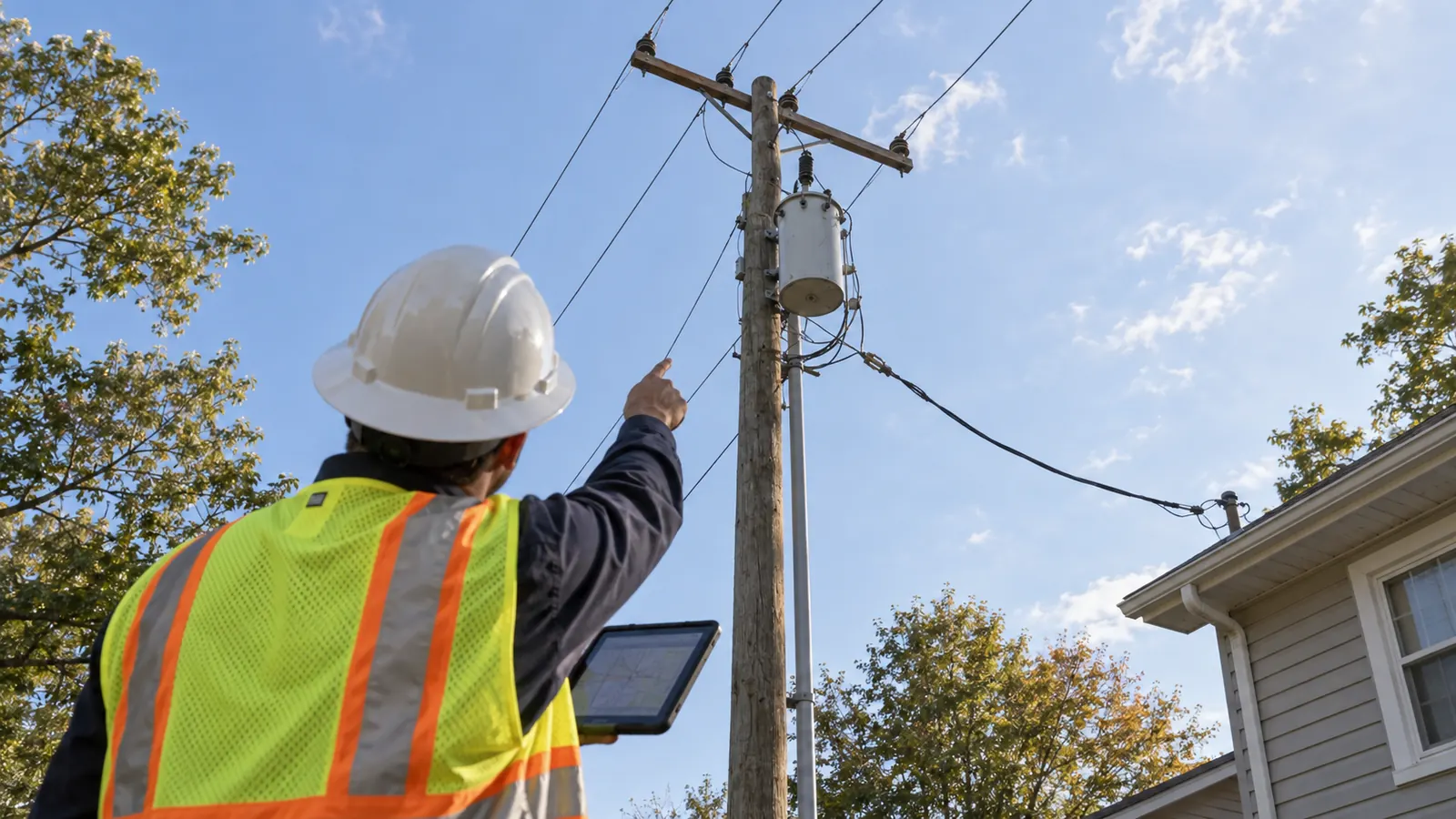
A distribution drawing can show a continuous line from a substation to a house while hiding several different engineering decisions. The feeder carries the combined load of a service area. Near the house, a transformer changes the voltage, and the service connection has its own physical limits. Those boundaries need to be clear before the route is ready for construction.
How an Electric Distribution System Works
An electric distribution system delivers power from a distribution substation through primary feeders and branch laterals to local transformers and customer services. For a common U.S. residential connection, the transformer supplies 120/240 volts. Following that path shows where the shared utility circuit gives way to the connection serving an individual property.
OSHA's Electric Power eTool, Illustrated Glossary, labeled February 2004, describes this residential voltage arrangement in its Distribution Systems entry. That is a useful reference for the basic equipment sequence, rather than a design specification for a particular utility. The serving utility determines the actual voltage and connection arrangement. Equipment selection and transformer placement on the plan depend on confirming those requirements.
The substation establishes the distribution source
At the distribution substation, a power transformer supplies the primary distribution voltage used by outgoing circuits. A bus provides a common electrical connection, and feeder breakers control the circuits leaving it. We carry each feeder's identity into the route drawings so a proposed extension can be traced back to the correct source. The closest visible pole may belong to a different circuit.
Feeders carry the area load; laterals branch toward customers
The primary feeder is the main distribution circuit extending from the substation. Primary laterals branch from it to reach smaller customer groups. A lateral can remain at primary voltage until it reaches a distribution transformer; calling a branch a lateral does not mean it is already at household voltage. We label the electrical function explicitly when a route includes several kinds of cable.
Many distribution circuits operate radially, with a single normal supply path to a given load. Other arrangements provide an alternate path through switching. Restoration planning depends on knowing which arrangement applies. Even a physically looped cable route may have an open point; its shape on the map leaves the normal supply path uncertain unless the operating arrangement is shown.
Electric Distribution System Components and Boundaries
At transitions, the equipment names help explain what changes electrically. Primary and secondary conductors can occupy the same corridor, but they serve different electrical functions. An overhead route can also become underground without changing its primary voltage. The component map below provides a way to discuss those distinctions while defining scope, before working through individual structures and construction details.
The local transformer changes voltage
A distribution transformer connects the primary circuit to the secondary system serving nearby loads. Pole-mounted units suit overhead construction; pad-mounted equipment is common where primary cables run underground. To determine how a new service fits the existing installation, we check the connection arrangement and the utility's equipment requirements as well as the enclosure location.
Voltage and capacity answer different questions. The required service voltage describes what the customer equipment receives. Transformer capacity describes how much load the unit is intended to carry under its applicable conditions. A proposed use that differs from the neighboring homes deserves particular attention: a transformer size familiar from those homes may be unsuitable for the new property.
| Component | Distribution function | Boundary to confirm |
|---|---|---|
| Substation feeder exit | Supplies an outgoing primary circuit | Feeder identity and connection limits |
| Main feeder | Carries load along the principal circuit | Normal supply path and section limits |
| Primary lateral | Branches toward a smaller service area | Phase arrangement and protective device |
| Distribution transformer | Changes primary voltage to service voltage | Primary terminals versus secondary terminals |
| Secondary and service connection | Delivers power toward customer equipment | Service point and ownership responsibilities |
| Switching and protection | Sections the circuit or interrupts faults | Device function and approved operating arrangement |
Secondaries lead to the service connection
Secondary conductors distribute power after the local transformer. The final overhead connection to a customer is generally called a service drop; an underground connection is generally called a service lateral. Keep the modifier attached because confusing these terms can put the wrong cable into a scope. A primary lateral branches upstream of the transformer; a service lateral belongs to the customer connection downstream.
The service point defines an important interface between the utility and customer installation. Ownership and installation responsibilities follow the serving utility's requirements, so we do not assume the meter marks every responsibility boundary. For a proposed extension, our distribution line extension design walkthrough explains how the service request becomes a route and an issued construction package.
Overhead and Underground Distribution Construction
Overhead and underground construction can perform the same electrical delivery function while creating very different physical work. The route must accommodate the selected equipment and remain accessible after installation. Start by comparing the actual corridor conditions. A short underground crossing within an overhead feeder, for example, needs transition details even though most of the circuit stays on poles.
Overhead construction depends on usable pole geometry
Poles support conductors and mounted equipment while maintaining the required physical separation around them. Span geometry influences the space the conductors occupy between supports. We check the space between poles too. A route that fits at each support can still encounter a conflict between them, especially where terrain or a crossing changes beneath the span.
Existing attachments affect what can be built. Adding distribution equipment may require a different pole arrangement or make-ready work before the proposed installation can proceed. An old drawing may overstate the room available in an established corridor if the attachments have changed. Our field verification must precede a promise that the existing structures can remain.
Underground construction depends on the whole cable route
Underground primary cables connect through equipment designed for that installation, with conduit or direct burial selected under the utility's requirements. The route must account for existing utilities and the space needed at equipment locations. Although the cable is hidden after burial, crews still need access to its terminations and room to replace a damaged section later.
A pad-mounted transformer needs a working equipment site with enough space for access within the property lines. Access must survive the finished development, including landscaping and fences. When a proposed cabinet sits where later grading would obstruct it, the apparent routing advantage disappears because the utility still needs a usable approach to the equipment.
Underground construction reduces exposure to some overhead hazards, including direct contact with falling branches along the buried segment. It introduces other constraints, such as excavation damage and difficult fault location. Outages remain possible, so the utility must accept an arrangement that addresses exposure and maintainability along the particular route.
These physical interfaces are where our electric utility engineering for distribution routes connects field information to construction drawings. We keep engineering 100% in-house. Draftech International provides full turnkey construction through Draftech-managed subcontract crews, with engineering and construction coordination kept within the same accountable delivery team.
What Distribution Protection Devices Do
A fault changes how the circuit behaves, and protective equipment responds according to its design and settings. The general objective is to interrupt the faulted path while limiting unnecessary loss of service elsewhere. When selecting equipment, we distinguish a switch used for isolation from a device rated to interrupt fault current. Their symbols may occupy similar places on a drawing, but their duties differ.
Breakers, reclosers and fuses interrupt current
A feeder breaker can interrupt a fault on its circuit when the associated protection calls for it to open. Reclosers can interrupt current and, where their programmed sequence permits, attempt to restore supply. Eaton's Fundamentals of Reclosers explains this trip-and-reclose function for temporary faults. A persistent fault can leave the device open after the permitted sequence rather than produce indefinite attempts to restore power.
For a fuse, interruption occurs when its element operates under the applicable current and time conditions, opening the protected path. Its placement can help confine an interruption to a branch or transformer connection. Selecting the fuse requires circuit information and coordination with protection elsewhere. The cutout's appearance gives no basis for assigning a generic fuse size.
Protection coordination considers how devices respond to the same event. The intended result depends on the utility's operating approach and the circuit conditions being evaluated. Readers who need the next level of project definition can use our guide to coordinating feeder protection. A limitation of our component overview is that it cannot supply an approved settings package or replace the utility's review.
Sectionalizing limits the affected portion of the circuit
Sectionalizing separates a circuit into portions that can be isolated. A conventional sectionalizer works with upstream interrupting equipment, opening during a de-energized interval in its coordinated sequence. Other switches support manual or automated isolation, depending on their ratings and controls. We identify each device's duty on the drawings; the broad word switch leaves its behavior unclear.
Surge arresters limit overvoltage at protected equipment, while voltage regulators help control operating voltage. Neither performs the fault-clearing duty of a feeder breaker. Our equipment schedules need to distinguish these functions so each required duty has the appropriate device.
Restoration also depends on the remaining circuit. An alternate connection must have an acceptable operating arrangement before a utility can use it to serve an isolated area. Ask the owner to identify the accepted restoration concept before depicting a tie as available capacity. The map should show what the utility has accepted, with unresolved connections clearly identified.
Our scope review also needs a place to record unanswered utility questions. We distinguish confirmed connection requirements from assumptions still awaiting acceptance, so an early drawing does not silently turn an unresolved choice into a construction instruction. That distinction matters when the route designer and the team reviewing customer service requirements are working from different revisions.
Recommended Next Steps for a Buildable Scope
Utility and cooperative engineers should establish the source and the normal circuit arrangement before releasing a route extension for detailed design. That decision tells the designer which equipment the proposed work must connect to and which section limits it must preserve. Resolve an uncertain feeder identity early: moving the connection point can change the physical route even when the customer location stays fixed.
Before finalizing the equipment area, developers and property owners need to obtain the utility's service requirements. A transformer placed on a preliminary site plan can conflict with the finished access route or the accepted service point. Bring the expected use and requested service arrangement to that discussion so the utility can assess the electrical connection the property needs alongside its parcel boundaries.
Construction managers should reconcile the issued drawings with the equipment schedule before mobilization. A substitution can change the space needed at a pad or the attachment arrangement on a pole. Have substitutions reviewed while the drawing can still be corrected, then record the final installation so operations receives a circuit description that matches what was built.
Project geography should be established at the same time as scope. Draftech's service-area information helps owners identify the location of a proposed route: Active in 24 states. Available across all 50 U.S. states. Confirm who will review the drawings through the local utility's acceptance process, which applies wherever the project is located.
Draftech International delivers turnkey telecom and power infrastructure from field survey through closeout. Our partner and company overview identifies the team behind that work. For distribution projects, we carry the planning into construction drawings and permits, coordinate with agencies, deliver construction through managed crews, and complete the as-builts and closeout. That continuity helps keep the service boundary and equipment access decisions intact as the project moves into the field.
For a route that needs an engineering starting point, consider Draftech's qualifying-route free-design offer. Draftech engineers the first 20,000 linear feet at no cost, from feasibility and field survey through permit approval; the owner reviews each request before Draftech commits the package. The review establishes whether the route qualifies before engineering begins. Bring the source connection and service requirements discussed above to that review; they help define what the line from substation to customer must show on the construction drawings.
Email info@draftech.com with your proposed distribution scope so we can review the connection requirements with you.