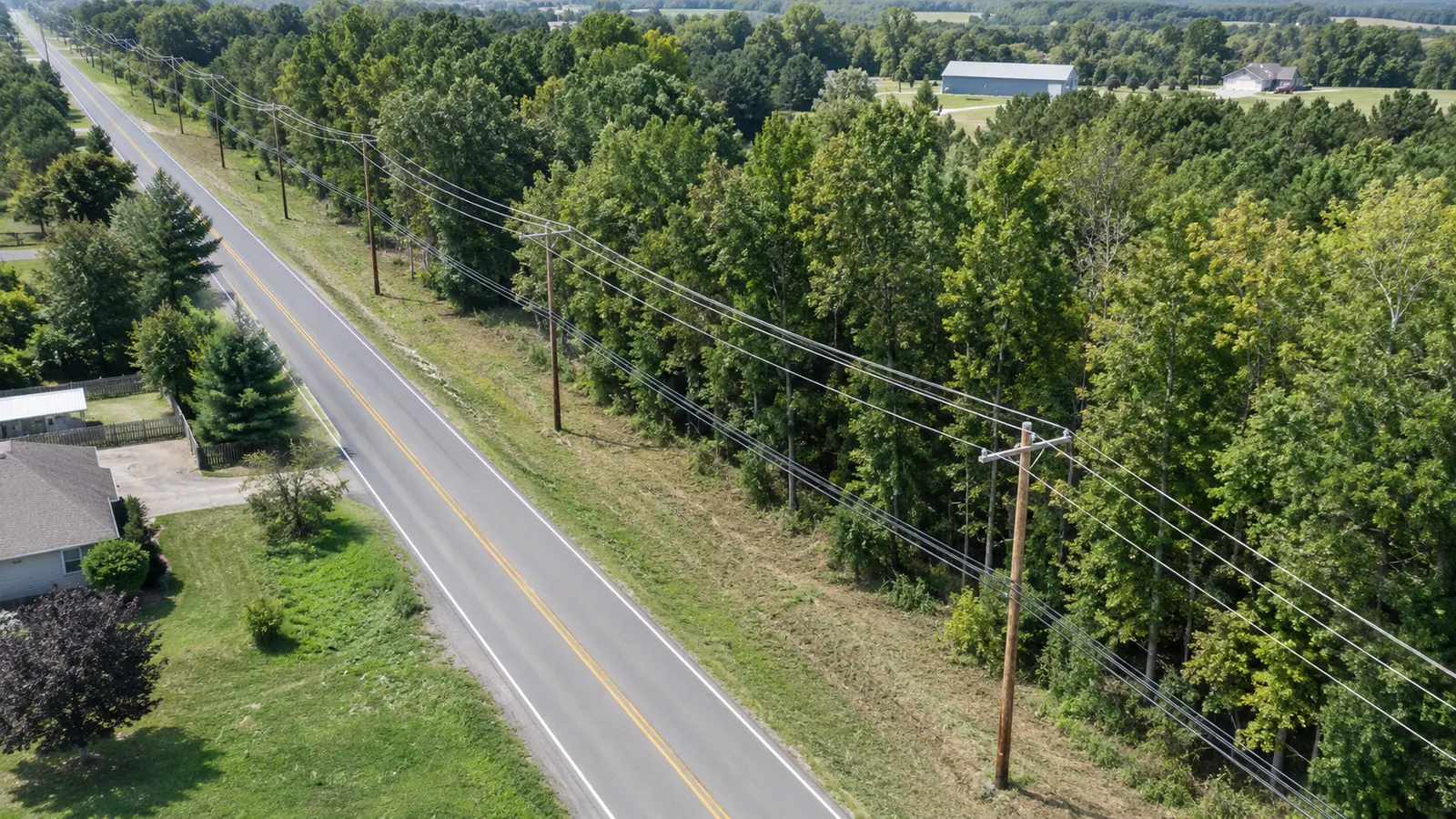
A clearance note becomes risky when its number is separated from the physical case that produced it. Road class and conductor relationship set the first boundary. Attachment type, sag, crossing geometry, and the edition the pole owner actually adopted then decide what the engineer has to check.
This guide is the reasoning record behind those checks. It does not reprint protected NESC tables, and it does not let a national summary stand in for licensed judgment, the pole owner's standards, or the edition the authority having jurisdiction has adopted.
Aerial Fiber Clearance Design Requirements Start with Authority
Aerial fiber clearance design requirements are the project-specific vertical, horizontal, and separation checks applied to a proposed communication attachment. As of 2026, IEEE C2-2023 is the National Electrical Safety Code edition in force. Part 2 covers overhead lines, but adoption, utility standards, permits, and site conditions still pick the controlling design case. Clearance is not guessed.
The first drawing note should name the governing source instead of saying NESC compliant. IEEE C2-2023 is a consensus safety code published by IEEE. A state, a local authority, a commission, a utility tariff, or an attachment agreement may adopt it and may add requirements. We confirm that hierarchy for the actual pole line before anyone uses a clearance value from memory.
Worker-safety rules sit in a different lane. Occupational Safety and Health Administration 29 CFR 1910.268 covers telecommunications work practices, including work near energized conductors. That rule is not a substitute for an overhead-line design table. A geometry check that passes does not, by itself, settle crew work methods. We keep those two authorities on separate notes so a construction instruction cannot masquerade as the engineering basis.
Write a One-Page Basis of Design Before Measuring
Our basis-of-design memo names the code edition, adopting jurisdiction, pole owner, applicable attachment standard, survey date and design loading assumptions. Unresolved conflicts are listed separately. It also states which measurements are field observations and which values came from owner records. We keep the memo to one page because its job is to stop two reviewers from applying correct rules from different editions, or from different utility supplements, to the same span. Span identity comes first.
Currency check: cite IEEE C2-2023 by full identifier, then confirm the edition and utility supplement accepted for the actual pole owner. Current publication status is not the same as local legal adoption.
The memo should flag known exceptions to the ordinary route: a limited-access highway, navigable water, a railroad corridor or transmission crossing. A structure approach is flagged as a separate case. Those cases can bring in another owner or permit. Some also require another engineering discipline. Naming them early changes the survey plan. It also stops a general communication-line criterion from being carried into a special crossing where the controlling geometry and the acceptance authority are not the same.
Survey the Clearance Case, Not a Generic Pole
A field record has to make the controlling relationship visible. The measurement origin for a roadway crown is not the origin for a supply conductor or a rooftop, and rail or water surface cases are different again. The survey scope says which object controls each check and how the measurement was obtained. A single pole-height attribute cannot answer that question.
Separate Pole Measurements from Span Behavior
Clearance is often controlled between supports, not at the pole face. Span length, attachment elevation, route angle, cable type, initial tension, final sag, temperature assumption, and loading condition all affect the proposed communication cable profile. The design package should keep both endpoint data and the modeled span condition. Otherwise a reviewer can verify the attachment height and still be unable to reproduce the lowest-point result over a road or driveway. The owner still decides.
Existing photographs help classify the case, but perspective can deceive. A camera angled upward can make two attachments look closer together. A long shot can hide a midspan dip. We use photos as corroborating evidence and measurements as quantitative inputs. When a feature is obstructed or unsafe to measure, the record says so. Guessing a conductor elevation from pixels creates precision the field team never obtained.
| Design question | Primary input | Authority check | Engineering output |
|---|---|---|---|
| Vertical ground or roadway clearance | Surface class, attachment elevations, span geometry, sag case | IEEE C2-2023 plus adopted owner criteria | Controlling span and margin record |
| Supply-to-communication separation | Conductor identity, elevations, hardware and crossing relationship | Applicable NESC rule and utility standard | Existing, proposed and make-ready condition |
| Building or structure approach | Structure geometry, accessible surfaces and cable path | Adopted code and permit conditions | Offset detail or route revision |
| Guy, anchor or riser conflict | Attachment geometry and work-space condition | Pole-owner construction standard | Detail, relocation or exception |
| Crossing of another line | Crossing angle, elevations and line classification | IEEE C2-2023 crossing provisions | Profile and responsible-party action |
This map keeps the survey aligned with the engineering question. The later aerial fiber installation design article covers hardware selection and cable placement details. It also addresses build sequence. Here the subject is narrower: the inputs and decisions needed to defend the clearance case. That boundary keeps both posts from repeating the same design-package checklist.
Survey confidence should travel with the value. Direct measurements, owner-furnished records, photogrammetric estimates, and inferred elevations do not deserve the same status. We may accept different evidence for an early route screen than for a construction release, but that choice has to be visible. When a roadway crossing sits near the accepted margin, we trace the result back through measurement method and modeled cable state before spending design time on a construction response. Measurements stay traceable.
Evaluate Clearances Without Inventing a National Number
Classification Comes Before the Table Value
IEEE C2-2023 organizes overhead requirements by defined conditions and line relationships. We first classify the case the span actually presents, including the surface, the crossing type, and the communication facility involved, before any table value is selected. Publishing one clearance number without that classification is not simplification. It strips away the facts that make the number valid.
Pole-owner criteria can be more restrictive, or they can prescribe a particular construction arrangement. An attachment agreement may require a standard detail, a communication-space organization, a tagging convention, or a make-ready sequence even when the underlying code check looks adequate. We list those owner conditions beside the NESC basis rather than calling them federal requirements. The reviewer can then see why a move was requested and who has authority to accept it.
- Code case: cite the specific IEEE C2-2023 rule family or table used, without copying protected table content into generic notes.
- Owner overlay: identify the utility standard, attachment agreement, or approved detail that changes the proposed arrangement.
- Measured condition: retain the source measurement and survey date. Keep the quality flag and modeled cable state behind the result.
One thing I have always found tempting in our own clearance workflow is to resolve every marginal case on the plan sheet. Some questions belong with the pole owner, another attacher, the authority having jurisdiction, or a licensed engineer responsible for a separate facility. A clean drawing cannot manufacture that authority. We issue an explicit request with the affected span and the consequence, then keep the design state open until the right party answers. Exceptions need a destination.
A reviewer should be able to reproduce the result from the surveyed geometry, the cable model, the loading assumptions, the applicable source, the controlling case, the calculated value and required margin. The proposed disposition completes the record. If one of those changes after make-ready, the record identifies the revision. That is the difference between a number placed on a drawing and an engineering check that can survive a second review.
When a case sits near the threshold, we run a sensitivity check because a small change in attachment elevation or span length can flip the conclusion. Surface classification and modeled sag receive their own checks against the field record. One limitation of this method is that it cannot rescue uncertain inputs by calculation alone. The reviewer should know which input controls the margin. That does not mean adding an arbitrary safety factor. It means testing the credible input range and writing down the project criterion. Better field work then goes toward the variables that could reverse the decision.
Convert a Clearance Failure into a Named Design Action
A failed check is not a complete make-ready instruction. The engineer still has to name the physical relationship causing the failure, the facility owner, the construction options that still exist, the dependencies, and the condition that will be rechecked after the change. Moving the proposed fiber may solve one separation and create another. A pole replacement may alter span geometry on both sides. The disposition therefore follows the network relationship, not one highlighted cell. This boundary prevents rework.
Do Not Confuse Pole-Access Timelines with Clearance Authority
Inside the coverage of the FCC pole-attachment rules, 47 CFR 1.1411 sets timelines for access to utility poles and includes a process for simple make-ready. Under the contractor-qualification rules, 47 CFR 1.1412(c)(1) requires agreement to follow available utility safety and operational guidelines, or NESC guidelines if those utility guidelines are unavailable. Those provisions matter to an attachment program. They do not supply the project's clearance geometry. We cite them for process timing and IEEE C2-2023 for the safety-code basis, subject to adoption and owner requirements.
The construction package should show the sequence needed to keep a safe, buildable state. If another attacher must move first, that dependency is visible. If a proposed attachment can proceed only after pole replacement, the release condition says so. If no practical arrangement exists, reroute is a design outcome, not a drafting failure. Each close has a different consequence. The span may move or remain after replacement. Another case may require redesign or a documented exception. Abandonment is also a valid disposition.
For measurement provenance, use the utility pole field-measurement evidence rules. For structural consequences, the pole attachment structural analysis guide explains why clearance and loading are related but separate decisions. Keeping those disciplines distinct helps us avoid claiming that a clear attachment is structurally acceptable, or that a passing pole model settles clearance. Release follows verified evidence.
Disposition rule: every failed clearance check should end with one physical action and one responsible party. It separately identifies the dependency state and condition for recheck. A red mark without ownership does not move the pole line toward construction.
Permit drawings and pole-attachment applications may present the same proposed cable differently, but the underlying geometry should reconcile. We compare stationing, pole identifiers, attachment elevations, crossing profiles, and make-ready notes across the package before submission. When one sheet depicts a moved cable and another retains the old height, that contradiction can generate a legitimate reviewer hold. Release depends on package consistency, not on running the calculation one more time.
Release the Clearance Record a Second Engineer Can Rebuild
Aerial Fiber Clearance Design Requirements at Final Review
Final review starts by detecting what changed since the last accepted survey, not by re-reading every span as if it were new. We compare the accepted survey with the proposed cable model. Make-ready dispositions and pole-owner comments are then reconciled against current plan geometry. A shifted attachment elevation or a revised route angle can change the controlling span without changing the pole identifier. The review log states what changed and which checks were rerun, so the sealed or approved package does not rely on stale calculations hidden behind an unchanged sheet number.
Small infill attachment: use a concise authority memo and a span exception list. A corridor-scale program needs machine-checkable inputs, with engineer review focused on crossings and marginal cases. Where ownership changes along the route, separate the criteria by pole owner. Never turn the strictest remembered value into a fictional national rule.
Our in-house OSP engineering team can carry field evidence through clearance analysis and make-ready coordination. Controlled design release remains the final engineering step. The partner-led Draftech engineering team remains accountable for that record. This service closes the gap between measurements and final geometry while preserving pole-owner authority and the licensed engineer's duty to apply current governing sources.
If the pole-owner criteria and route evidence are already in hand, email info@draftech.com with the governing standard and attachment request. Identify each unresolved crossing separately. To start from a blank pole line, request a clearance-design scope review.
The release decision is not whether every number looks comfortable. It is whether each controlling case can be traced from source authority to observed geometry. The release then links the modeled condition to its engineering result and owned action. When that chain is intact, another engineer can rebuild the review. When it is missing, construction inherits an unexplained number and the risk attached to it.
Archive the calculation inputs with the released package, not only the plotted result. Pole replacements and road improvements can force a later reassessment. New attachments or owner comments can do the same. A durable record lets the next engineer determine whether the changed condition invalidates the original case. Maintenance and future attachment teams can then read the basis instead of reverse-engineering a faded clearance label from a plan sheet.
Record review should also compare the proposed cable with planned roadway and utility work already known to the owner. A clearance that passes against today's geometry can become obsolete before construction if a pole replacement or road profile change is already scheduled. A planned supply facility can also invalidate the snapshot. We identify those pending conditions as dependencies and state the date of the evidence checked. The design can then hold, coordinate, or proceed with a documented contingency instead of treating a transient snapshot as permanent plant.
If the pole line you are reviewing is the start of a new route, the first 20,000 linear feet can be engineered at no charge. Our free permitted design package carries that opening segment from field survey through clearance analysis and make-ready, all the way to permit approval. You keep the files either way.