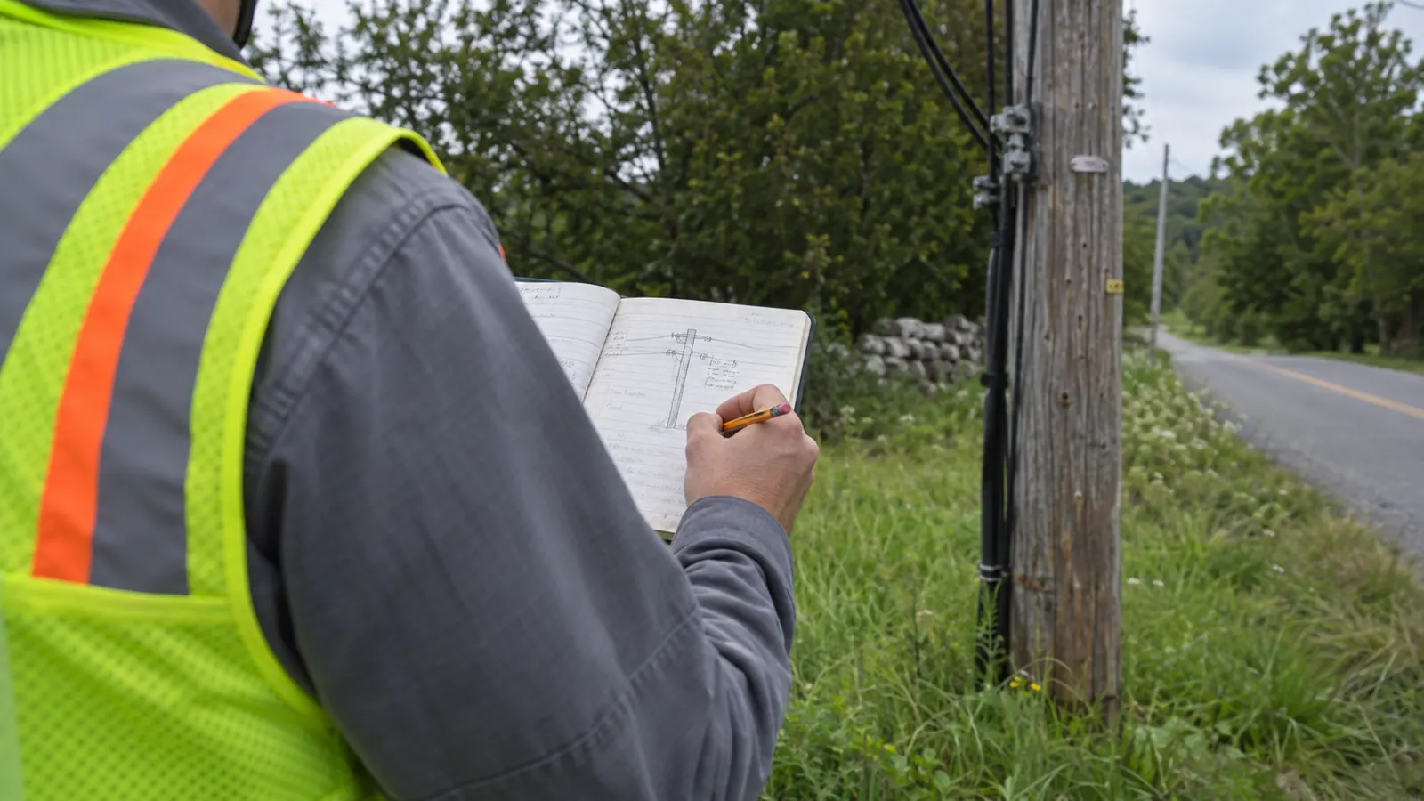
- What Information Is Collected During OSP Fielding?
- Pole Records: Identity and Dimensions; Attachments
- Spans and Clearances: Measure the Space Between Poles
- Ground Conditions: Alignment and Construction Access
- Underground Structures: Visible Records and Verification Gaps
- Next Steps: Specify What Information Is Collected During OSP Fielding
A pole photograph can be sharp enough to read a tag and still leave the designer unable to place a cable. The missing information may be the attachment height at the next pole, or whether the ground rises beneath the span. We need the relationship between assets, not just a collection of pictures.
This catalog explains what information is collected during OSP fielding and how it enters design. We cover aerial records and underground observations, then identify the gaps that require further investigation. For the broader survey workflow, use our existing infrastructure survey guide.
What Information Is Collected During OSP Fielding?
What information is collected during OSP fielding? We group the design inputs into 6 categories: pole identity and dimensions; attachments and photographs; span geometry; clearances; ground conditions; and underground structures. We connect each observation to its asset so engineers can evaluate the proposed route.
Scope determines collection depth. A preliminary route walk may locate accessible structures without measuring every attachment. A design survey needs the detail required by the receiving engineer and facility owner. We establish that distinction before mobilization, because a location inventory cannot become a loading survey simply by changing the name on the delivery folder.
Asset identity and measurement provenance
A stable asset ID connects the field record to the drawing. We retain the owner's pole number or structure identifier separately from our project identifier, and we record an unreadable tag as unreadable. Replacing it with a nearby pole's number creates a convincing error: the map may look correct while the attachment application refers to another structure.
Coordinates need a stated reference system and a collection method. Units matter. A designer receiving elevations also needs the vertical datum, because an elevation from one reference cannot be compared directly with a height measured above local ground. We keep the original observation available when a corrected coordinate enters the working model, rather than making the correction erase its own history.
Record the observation date. We associate photographs with that visit and flag later changes, particularly replacement poles or disturbed ground. An older photo can remain useful evidence, but it should not appear to verify a condition observed after the photograph was taken. Our review must be able to distinguish a new measurement from a copied attribute.
Keep observations separate from interpretations
Measurements differ from interpretations. The field record might show a cable entering a riser while its destination remains uncertain. We can draw the visible riser with confidence; continuing that line underground requires other evidence. Record the unresolved connection explicitly so the designer knows where an investigation ends and an assumption would begin.
For missing information, use a distinct status such as MISSING or not accessed, with a reason. Zero is a value. A blank clearance field should never turn into a zero-clearance conflict during an import, and an uninspected duct should never become an empty duct through a default setting. We check those translations before the survey file becomes a design reference.
Funding conditions belong beside the technical scope, without replacing it. The separate BEAD fielding scope discussion addresses the added documentation question. Here, the useful distinction is simpler: a funding label does not tell an engineer which cable crosses the road or whether a photographed structure connects to the next one.
The deliverable format should expose these distinctions without making the designer open every photograph. We use separate fields for a collected value and its verification status, with a linked note when the value needs attention. That lets the receiving team locate unresolved inputs before drawing around them, while retaining the photographs for closer review of the actual condition.
Pole Records: Identity and Dimensions; Attachments
Record the support and its attachments. We separate those attributes because changing the proposed cable affects the attachment model, while correcting the pole's class changes the structural basis. The table maps the field evidence to the decision it supports; it does not turn an observation into permission to build.
| Data category | Field record | Design use |
|---|---|---|
| Pole identity and dimensions | Tag, marked length and class, material, visible condition | Select the existing support and flag uncertain structural inputs |
| Attachments and photographs | Attachment heights, identifiable facilities, equipment, linked views | Develop occupancy and loading inputs; document visible conflicts |
| Span geometry | Endpoint IDs, horizontal distance, direction, elevation difference | Lay out the route and establish span model geometry |
| Clearances | Measured separation and crossing location, with observation conditions | Evaluate the proposed arrangement against applicable criteria |
| Ground conditions | Surface type, grade changes, access limitations, visible obstructions | Assess alignment and construction access; scope further investigation |
| Underground structures | Structure IDs, dimensions, visible duct entries, inspection limits | Plan pathway connections and equipment space; assess reuse evidence |
Pole height and class are separate inputs
Record the marked pole length and strength class where legible, with a close photograph of the marking. Overall pole length is not the same as exposed height above ground. We retain both fields when the survey measures exposed height, and we do not infer embedment from a photograph. Material and visible condition also belong to the record used for structural review.
A damaged surface or a leaning pole needs a location-specific note. Fielding cannot establish remaining pole strength. Keep that limitation visible. We flag the observation for the pole owner or the required inspection process, keeping the uncertain input out of a finished capacity claim. A class selected from appearance alone can make a loading model precise about the wrong pole.
Attachments need heights and identifiable connections
Document the vertical position of each relevant attachment and identify the facility where the available evidence supports it. Equipment attached to the support also affects the model. We record visible guying and anchor relationships, including direction, so the engineer can determine what additional measurements are needed. An unconfirmed cable type remains unconfirmed until the owner record or another accepted method resolves it.
Photographs should explain the geometry that the attribute sheet cannot. A pole overview gives context; a closer view can resolve an obscured connection, and Katapult Engineering's article, Utility Pole Field Data Collection: Why It Starts At The Pole, identifies pole markings and grounding as details that require close observation. Its distinction supports collecting evidence at the structure instead of relying entirely on corridor imagery.
Keep the original frame: Preserve the source photograph when adding measurement annotations. A reviewer needs to inspect the underlying attachment without having to interpret a label drawn over it.
Spans and Clearances: Measure the Space Between Poles
The span belongs to both endpoints. We identify the connected poles and the direction of the span before treating its length as a design input. A line drawn between nearby coordinates may connect the wrong supports, especially where the route branches or parallel pole lines share a corridor. That error changes the modeled load path.
Span length, direction, and changes in grade
Distinguish horizontal span length from sloping distance and from installed cable length. They answer different questions. The engineer needs the distance definition and endpoint geometry to use the measurement correctly; cable quantities also depend on the designed sag and allowances. We carry the line direction and relevant ground profile into the design review rather than calculating cable quantities from a map line alone.
A route can dip through a drainage channel while the wire remains high, then cross rising ground before the next support. The lowest clearance need not occur at the geometric midpoint, so our field scope should capture the controlling crossing or obstruction, with enough location detail for the designer to reproduce the check. A midpoint value without its surrounding profile can hide that condition.
Observed clearance and design compliance
A clearance record identifies what was measured and where the measurement applies. For a roadway crossing, the relationship between the cable and the traveled surface matters; a height above the shoulder describes a different location. We also retain the measurement method and observation conditions where they affect interpretation, because cable sag at collection is an existing condition, not the complete set of design conditions.
The engineer evaluates the proposed attachment using the applicable code and owner criteria. We do not insert a universal clearance number into every route file, because crossing use and facility configuration can change the governing requirement. Where poor visibility prevents a defensible measurement, the fielding package should request a return visit or another accepted collection method instead of supplying a guessed pass.
Missing span context is a field-to-design problem our OSP engineering and field services are intended to resolve. We connect the observations to the proposed arrangement before issuing drawings. A measured separation may expose a conflict, but the remedy still requires engineering and the affected owner's review.
Ground Conditions: Alignment and Construction Access
The ground record explains whether a proposed alignment has room to be built and maintained. Pavement edges and drainage features help orient that review. We distinguish a physical access constraint from a property-rights question: a visible opening between fences does not establish permission to enter, and an apparent shoulder does not establish the right-of-way boundary.
Surface conditions and working space
Record surface type and observable grade changes along the proposed path, tied to a route segment or station. Note obstructions with enough context to assess the affected work area. A tree beside a proposed handhole matters differently from a tree across the only equipment access, even if both photographs receive the same vegetation label. We need the consequence at that location.
Surface observations guide restoration and installation planning. They cannot establish subsurface geology. We keep visible rock or wet ground as observations and identify when geotechnical investigation is needed, rather than converting the appearance of a ditch into a confident prediction about the entire bore path. The designer should see the limits before choosing a construction method.
Photograph the approach: Include the access path to a proposed work area when its width or grade could constrain equipment. A close photograph of the placement point alone may omit the condition that makes it unusable.
Our preferred digital forms have a weakness: a required dropdown can make a field record look more certain than the observation supports. We need an unknown option and room for a useful note. Otherwise, the collector may choose the nearest available label, and the office receives a clean dataset that describes a condition nobody actually confirmed.
Underground Structures: Visible Records and Verification Gaps
A lid locates a structure. We record the structure identifier and accessible exterior condition before describing any interior. Opening or entering a structure requires the appropriate authorization and procedures. If access is unavailable, the deliverable should say what was observed from outside and what remains uninspected, with no implied interior survey.
Structure dimensions and duct entries
Where authorized inspection permits it, collect internal dimensions and the visible arrangement of duct entries. Duct size and apparent occupancy should be associated with a particular wall or entry position. We also need to know how the structure relates to the next recorded asset, because a count of occupied openings does not reveal which cable follows which route beyond the wall.
Document usable space around existing equipment where it affects a proposed closure or cable arrangement. Water or sediment can limit what is visible. We avoid describing an obscured opening as blocked unless the evidence establishes a blockage, and we avoid calling a visible empty opening a usable end-to-end duct. The vault and manhole survey guide addresses the detailed interior record.
Utility evidence and pathway continuity
Surface markings and available owner records help identify where further investigation belongs. We preserve their source and date instead of promoting a line copied from a record drawing into a measured underground alignment. The map should communicate uncertainty at the affected segment.
Reuse needs more than endpoints. Confirmation may require authorized pathway testing or additional investigation, depending on what the proposed installation demands. We carry that need into the design issue list and keep unverified capacity out of the cable-placement decision. An interior photograph can support a dimensional check inside the structure while leaving the connected duct's condition entirely unresolved.
Next Steps: Specify What Information Is Collected During OSP Fielding
For an aerial network owner: Require attachment-level records tied to verified pole identities, with the connected spans included. Review the unconfirmed pole attributes before commissioning the loading work. Otherwise, the engineer may have to reopen the structural model after the first apparent result, because its support data never matched the field evidence.
For an underground route planner: Separate accessible structure observations from pathway verification in the collection scope. Specify what evidence will support a reuse decision and who supplies it. That distinction lets the designer advance confirmed portions without presenting an untested duct connection as available capacity for the proposed cable.
For the receiving design team: Check a representative record against the intended design import before accepting the full dataset. Confirm that the photo opens and that missing values retain their meaning. A successful file transfer proves very little if the designer cannot reconstruct the connection between a measurement and the asset it describes.
Discuss the missing field records on your route. Bring the collection scope and a sample record so the engineering team can identify the next investigation.
Draftech keeps engineering 100% in-house, so unresolved field measurements can return to the people developing the drawings. Our engineering and full turnkey construction services connect that design work to delivery through Draftech-managed subcontract crews. Active in 24 states. Available across all 50 U.S. states. For a collection scope that needs review, email info@draftech.com.
If missing field evidence is holding up a route, the free design offer provides a way to request an engineering package: Draftech engineers the first 20,000 linear feet of a qualifying route at no cost, from feasibility and field survey through permit approval. The owner reviews each request before Draftech commits the package.