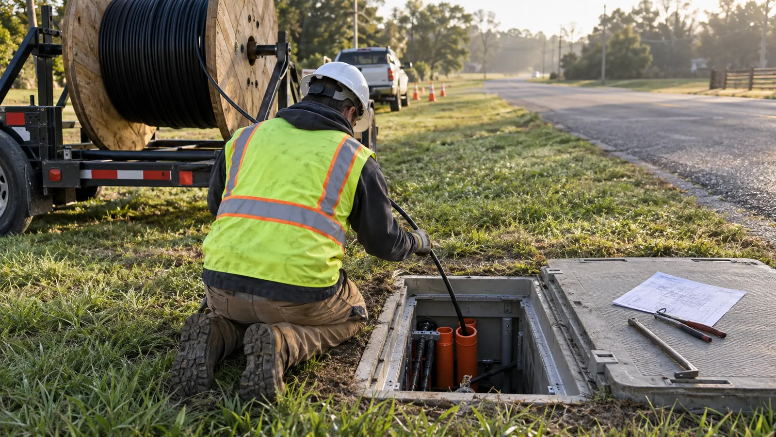
- Underground Fiber Optic Cable Installation: Plan the Route
- Locates and Utility Verification Before Excavation
- Compare the Four Underground Installation Methods
- Conduit, Innerduct and Access Structures
- Tracer Wire, Restoration and Installation Acceptance
- Underground Fiber Optic Cable Installation: Choose by Corridor
A fiber route can be ready for cable while still being unready for construction. The missing decision may be how to cross a driveway, where to set a handhole or what pavement repair the authority will accept. Equipment selection follows those decisions, and a production schedule built ahead of them carries unresolved civil work into the field.
We approach underground installation as a connected route from the first excavation through acceptance. This guide compares the available methods and explains the pathway details that determine whether a contractor can install the cable and leave the owner a maintainable network. The approved construction documents govern the actual work.
Underground Fiber Optic Cable Installation: Plan the Route
Underground fiber optic cable installation places optical cable below ground, directly in suitable soil or inside a duct system. The 4 methods covered here are open trench, directional boring, plowing and microtrenching. Selection depends on the approved corridor, existing utilities, ground conditions and the surface that must be restored after construction.
A route needs more than a line on a basemap; we start by identifying where the owner has permission to build and where maintenance personnel will be able to return. A narrow easement may accommodate buried conduit while leaving too little room for a drill setup or a splice trailer. Those access constraints belong in the design before a contractor commits equipment.
Divide the route where conditions change
We recommend assigning the installation method by segment rather than giving an entire project one construction label. An open shoulder may support plowing until the route reaches a paved entrance; that crossing may call for a bore, followed by a trench into the next handhole. Each transition needs a defined connection detail. Otherwise, separate crews can finish their assigned footage and still leave a discontinuous duct path.
Workfront readiness controls the sequence. We want the construction drawing to distinguish a segment released for work from one awaiting a crossing decision. Mark the limits where the approved method changes, and tie those limits to the restoration detail. A contractor pricing an unresolved crossing should identify that assumption explicitly so the owner can compare bids on the same scope.
Set burial depth from the governing detail
There is no single burial depth that applies to every underground fiber route. Required cover depends on the right-of-way authority and the approved design, with different treatment possible at crossings or in a permitted microtrench. We distinguish cover above the installed facility from the depth to the trench bottom. A drawing must identify the measurement reference so the inspector and contractor check the same dimension.
Future grading matters too. A ditch that will be regraded can leave less cover than the installation survey suggests, while a future road section may change the surface used as the reference. We resolve that interface with the authority before construction. Where the required cover cannot be achieved, the designer must obtain an accepted alternate detail rather than letting the field crew improvise a shallow segment.
Locates and Utility Verification Before Excavation
Utility markings establish where further investigation is needed. They do not establish every crossing elevation. OSHA's current 29 CFR 1926.651(b), Underground installations, requires estimated utility locations to be determined before excavation and exact locations to be established by safe and acceptable means as work approaches them. The practical consequence is a planned verification step before the equipment reaches a conflict.
Start with the applicable 811 process. Confirm the ticket covers the actual work area and that the required responses have arrived before excavation begins. The notice period and ticket validity depend on the jurisdiction. Private facilities can require separate locating arrangements, so we ask who owns the plant inside the property boundary instead of assuming the public locate request covers it.
The field team should reconcile marks with the design and resolve discrepancies before releasing the affected segment. Where verification exposes a conflict, record its position against the proposed facility and return the decision to the designer. Our underground duct bank survey guide explains the survey information needed when an existing duct route is part of that decision.
Keep verification ahead of production. Put unresolved utility crossings on the workfront plan with a named person responsible for clearing each one. Moving the crew to an approved segment protects the schedule without treating an unanswered conflict as permission to excavate.
Compare the Four Underground Installation Methods
The method comparison starts with what the corridor can tolerate. Vermeer's guidance, Choosing the right installation method for underground utilities, distinguishes open-cut methods from horizontal directional drilling by ground conditions and surface constraints. We use that distinction to frame the choice, then check the permit and the construction access available at each segment.
| Method | Useful route conditions | Main constraint | Restoration focus |
|---|---|---|---|
| Open trench | Accessible corridor needing an exposed installation path | Excavation footprint and safe access | Backfill quality and surface reconstruction |
| Directional boring | Crossings where continuous surface excavation is restricted | Verified conflicts and a feasible bore profile | Pits and any disturbed setup areas |
| Plowing | Long, accessible runs in suitable ground | Obstructions and control of placement | Ground settlement and disturbed vegetation |
| Microtrenching | Approved narrow-slot routes in suitable pavement | Authority acceptance and pavement compatibility | Slot preparation and specified reinstatement |
Open trench: direct access to the installation
Open trenching exposes a continuous path for placing the specified conduit or direct-burial cable. It allows observation of the installation before backfill, which is useful when the work includes multiple ducts or complicated structure entries. The tradeoff is surface disturbance. An accessible shoulder and a finished paved corridor create very different excavation and reinstatement obligations, even when the installed cable is identical.
Inspection must happen while the work is visible. We recommend a hold point for the installed duct and its bedding before concealment, with the acceptance criteria taken from the approved detail. The contractor also needs an excavation safety plan appropriate to the work. Productivity assumptions should account for protecting the excavation and maintaining access, rather than measuring only how quickly the trench can be opened.
Directional boring: preserve the surface between pits
Horizontal directional drilling, commonly called directional boring, creates a guided underground path and pulls the specified duct into it. A roadway crossing can therefore avoid a continuous open cut across the pavement. Entry and exit locations still require room, and the planned profile must accommodate the duct's allowable bend and the available clearance around existing facilities. The surface remains part of the design.
A bore requires a feasible profile. We check whether the proposed approach can enter and leave the crossing without forcing an unacceptable bend at the receiving structure, especially where a short setback limits the drilling geometry. The contractor's execution plan must address ground conditions and drilling-fluid control. Unexpected conditions need a defined response, including who can approve a revised alignment before work continues.
Plowing: continuous placement in suitable ground
Plowing places suitable cable or duct through a narrow ground opening behind the plow blade. Prysmian's Buried Cable Installation Practices, Issue 3, identifies open or rural areas as candidates for this method and describes the limitations created by obstructions. It can suit a long accessible corridor, but the route still needs utility verification. A visually empty shoulder can contain buried service crossings.
Ground suitability decides whether the apparent production advantage survives. We want the contractor to identify areas where rock or abrupt terrain changes could interrupt placement, and to show how those sections will connect to the plowed run. Direct burial also commits the owner to a different replacement strategy than ducted construction. Specify a cable rated for the installation environment and resolve future access before selecting it.
Microtrenching: a narrow slot with a specific pavement detail
Microtrenching cuts a narrow slot for a compatible cable or microduct system, commonly within pavement. The Fiber Optic Association's Fiber Optic Installation By Microtrenching describes this as a distinct construction approach. Its suitability depends on authority acceptance of the complete installation detail, including the slot location and reinstatement. A narrow cut alone does not settle the long-term maintenance question.
We ask about planned resurfacing before proposing the slot alignment. The design must address how later pavement work will interact with the installed plant and how the route enters access structures without leaving exposed transitions. Compare these obligations in microtrenching versus traditional trenching for fiber. Select microtrenching where the approved pavement system supports it, rather than treating it as a substitute available everywhere.
Conduit, Innerduct and Access Structures
The buried pathway determines how the owner can add or replace cable later: conduit provides the main protective path; innerduct divides usable space inside a larger conduit or creates a dedicated cable pathway. A microduct system must be compatible with the selected cable and placement equipment. We review the pathway as a connected system, including its transitions, rather than approving components independently.
Size the pathway for cable placement
Pulling and blowing impose different requirements on the duct system. Corning's Standard Recommended Procedure 005-011, Duct Installation of Fiber Optic Cable, addresses cable handling during a duct pull, including tension and bending control. Use the selected product's installation limits. A diameter that appears adequate on a cross-section may still leave a difficult pull when the actual route includes several bends.
Prove the installed duct before placing cable. Specify the cleaning and proving procedure in the construction package, and record acceptance by duct segment. If blowing is selected, check the system's applicable pressure-test and coupling requirements with its manufacturer. Spare pathways should be identified and sealed. A spare shown on the drawing has little operating value if the owner cannot determine where it terminates.
Place handholes and vaults around the work they serve
Handholes and vaults provide access for cable placement or splicing, but their names alone do not establish their dimensions or load capacity. Select each enclosure for the actual installation and expected surface loading. The layout must preserve cable bend limits and leave workable space for the closure. Maintenance access should be considered before the location becomes fixed by the civil design.
We also review where the maintenance vehicle can stop. An enclosure placed beyond the usable shoulder may satisfy a plan offset while making routine access difficult. The structure schedule should connect the enclosure identifier to its approved detail, including the entry arrangement. Where entry into a vault is contemplated, the contractor must evaluate the applicable confined-space requirements and work procedures before personnel enter.
For owners coordinating those interfaces, our fiber construction management services connect design decisions with field acceptance. Draftech International delivers turnkey telecom and power infrastructure from field survey and planning through construction drawings, permits, agency coordination, construction, as-builts and closeout. Engineering is 100% in-house. Full turnkey construction is delivered by Draftech-managed crews under Draftech's QA/QC and safety program.
Tracer Wire, Restoration and Installation Acceptance
A dielectric cable inside plastic duct needs an intentional locating provision. Where tracer wire is specified, treat it as a complete locating system with accessible connections and an accepted termination arrangement. Copperhead Industries' Complete Utility Locating System guidance explains the need for a circuit and connection access. We recommend verifying the installed system before the route is accepted.
Demonstrate the locate path. Include a field tracing check in acceptance so the owner can confirm that the intended signal follows the installed route. A continuity result alone cannot show that the wire and the mapped duct follow the same alignment.
Restoration begins with the condition survey. We recommend recording the affected surface before work so later acceptance can distinguish existing damage from construction damage. The approved restoration detail should establish the reinstatement limits; a narrow excavation can still require a wider pavement repair. Compare the complete civil scope in aerial versus underground fiber construction cost before assigning a budget to the underground option.
Separate civil completion from optical acceptance
A restored surface and a tested cable answer different questions. Civil acceptance addresses the buried installation and the reinstated corridor, while optical acceptance establishes whether the installed fiber meets the specified performance criteria. The FOA's Outside Plant Construction Guide: Underground Cable Installation treats cable placement as a separate activity from building the underground pathway. Schedule the testing required by the network owner's acceptance specification.
The closeout record must preserve what will be hidden. We recommend capturing approved alignment changes while their locations are still observable, then reconciling them against the installed structure identifiers before the drawings are finalized. Tie test results to those same identifiers. An owner trying to investigate a later fault needs to connect a cable record to an actual route without guessing which field revision was installed.
Underground Fiber Optic Cable Installation: Choose by Corridor
For a rural network owner: evaluate plowing on accessible segments with suitable ground, and reserve separate methods for verified obstructions. Decide whether replacement access justifies conduit before finalizing the cable specification. We recommend comparing the whole route, including method transitions, because an attractive production assumption can leave the difficult crossings outside the apparent scope.
For an urban overbuilder: confirm the pavement authority's accepted details before choosing between trenching and microtrenching. Where surface excavation is restricted, develop the boring profile and verify that equipment can occupy the proposed setup area. Put restoration limits into the bid documents so the owner receives comparable offers and can see which contractor has allowed for the actual civil obligation.
For an owner extending an existing network: investigate available conduit before procuring new excavation. Confirm usable capacity and access at the receiving structures, then select cable placement around the verified pathway. We recommend resolving ownership and maintenance responsibility at that interface before construction starts. Existing infrastructure can save civil work only when the project has both permission and a usable path.
Draftech coordinates unresolved crossings and structure-entry details through the same delivery team that carries the route into construction and closeout. Active in 24 states. Available across all 50 U.S. states. To discuss a route with uncertain civil scope, contact info@draftech.com with the proposed alignment and the authority's known requirements.
For a route still moving toward a buildable package, the first 20,000 linear feet engineering offer can support that preparation: Draftech engineers the first 20,000 linear feet of a qualifying route at no cost, from feasibility and field survey through permit approval. The owner reviews each request before Draftech commits the package.
Discuss your underground route with Draftech. Bring the crossing constraints into the construction plan before they become field changes.