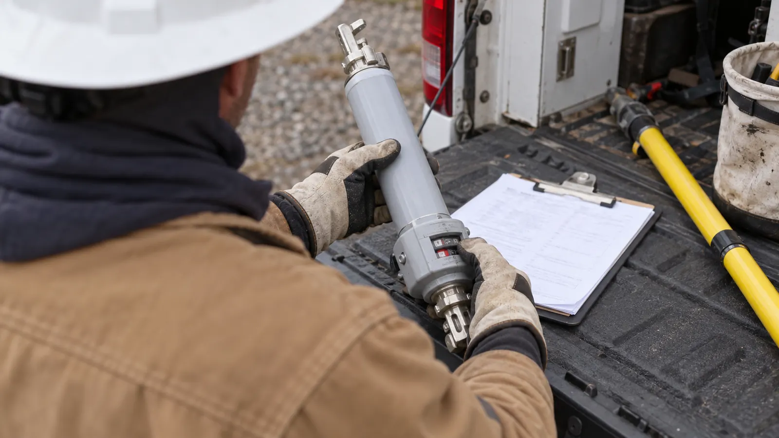
A device on a feeder drawing can look like a straightforward replacement for a fuse. Its operating role may be quite different. We start by asking which device interrupts the fault and which device opens afterward, because that distinction changes the equipment specification and the physical installation the utility must accept.
For utilities and electric cooperatives, the useful question extends beyond the definition. We need to know which customers fall behind the proposed opening point and whether the selected equipment fits the structure. This explainer connects that operating concept to distribution design without prescribing settings for a particular feeder.
What a sectionalizer does during a feeder fault
A sectionalizer is an automatic line device that isolates a feeder section after counting qualifying fault-current interruptions by an upstream protective device. In a hypothetical 2-count sequence, it opens during the recloser's second dead interval, allowing a later reclose to restore the healthy circuit while the faulted branch stays disconnected.
The upstream device clears the fault current. The sectionalizing device waits for the circuit to be deenergized before its automatic opening operation. That division of work explains why a switching symbol alone tells us too little about an installation. We also need the operating function and the equipment's documented capabilities, including any separately rated manual load-switching function.
Follow the current path before counting operations
Consider an illustrative radial feeder with a recloser ahead of a branch sectionalizer and a persistent fault on that branch. Fault current flows through both devices. When the recloser opens, it interrupts that current; the downstream device registers a qualifying event under its sensing logic. The count belongs to the device that saw the fault current, rather than every device that happened to lose supply.
The recloser closes again. If the fault persists, another qualifying current pulse and interruption can advance the count. When the selected count is reached, the downstream contacts open during the dead interval, before the upstream device's next permitted closing operation. The healthy portion can then regain supply. Customers behind the open point still await repair or another utility-approved supply arrangement.
This example explains the sequence, not a setting recommendation. Actual operation depends on the selected equipment's sensing logic and the utility-approved scheme, especially where supply can arrive through another path or connected generation changes the electrical conditions. We carry the approved device function into the drawings rather than treating a familiar symbol as enough information to purchase equipment.
Temporary faults and the reset function
A temporary fault may disappear before the opening count is reached. Supply returns successfully. The counting mechanism must then reset according to the equipment's design, so unrelated events do not automatically accumulate into an unintended opening. We ask the owner to identify the accepted reset behavior in the equipment requirements; a generic description of a counting device cannot establish that behavior for every model.
The upstream operation also affects healthy customers who share its interrupted circuit. Sectionalizing can limit the portion left disconnected after the sequence, but the preceding interruptions still occur. That is a real limitation of the count-and-open approach. We would not promise that adding a branch device eliminates momentary interruptions for everyone upstream of its contacts.
Drawing review: Label the upstream interrupting device and the downstream opening point separately. A reviewer should be able to follow their electrical relationship without inferring it from equipment proximity on the sheet.
Sectionalizer versus recloser and fuse
These devices solve different parts of a feeder problem. We compare their functions before discussing mounting hardware, because substituting one for another can change how the circuit behaves even when the replacement fits the existing support. Our recloser engineering overview provides context for the upstream equipment; the distinction here is the downstream device's dependence on an interruption elsewhere.
A fuse responds to current through its element and clears within its applicable interrupting capability. A recloser can interrupt fault current and make subsequent closing attempts under its control. A conventional counting sectionalizer opens after another device has removed fault current. Physical appearance can overlap. The equipment description must identify the function being supplied, including when a multifunction device is configured for sectionalizing service.
| Design question | Counting sectionalizer | Recloser | Fuse |
|---|---|---|---|
| Who interrupts fault current? | An upstream protective device | The recloser, within its rating | The fuse, within its rating |
| What initiates isolation? | Qualifying count followed by a dead interval | Protection and control operation | Current acting on the fuse element |
| Does it make automatic closing attempts? | Do not assume this function | As enabled by the approved control scheme | No |
| What happens after operation? | Return follows the device design and utility procedure | It may reclose or remain open under its control | The operated element requires replacement |
| What must drawings distinguish? | Opening function and upstream dependency | Interrupting equipment and control interfaces | Fuse assembly and approved element specification |
Fault interruption and load switching are separate capabilities
Opening ordinary load current and interrupting fault current place different demands on equipment. Keep the ratings separate. A device may include a load-interrupting feature without being intended to clear a short circuit through its sectionalizing action, so we require the submitted equipment data to describe each claimed capability explicitly. The installation detail should not turn an optional function into an assumed feature.
The same distinction applies to a manual operating handle. Its presence says little about the electrical duty permitted during use. We show the operating arrangement required by the accepted design and leave switching execution to qualified utility personnel working under the owner's procedures. Neither a handle illustration nor an open-position indication establishes that a circuit is safe to work on.
Choose the maintenance obligation deliberately
An operated fuse element must be replaced before that fuse assembly can return to service. A sectionalizing device avoids consuming a fuse element as part of its normal opening action, but it still needs an accepted restoration procedure and equipment maintenance. Reset methods vary. We ask what the owner expects after an operation before specifying a replacement that changes the field crew's established work.
We favor keeping the approved equipment identity visible throughout procurement. A proposed substitute that fits the mounting holes can still differ in sensing or operating features. Require the utility's review of that difference before the substitution reaches the construction set, and keep the accepted assembly drawing with the equipment schedule so installation does not depend on a catalogue image.
Where utilities place sectionalizing points on feeders
Placement defines an electrical boundary. A device at the head of a lateral can separate that branch from the feeder supplying it; a device farther along a main line creates a different downstream area. We begin with the owner's intended isolation boundary and trace the actual connectivity before choosing a pole or enclosure location. Geographic closeness does not establish electrical order.
Lateral entrances and main-line sections
A branch entrance is a useful place to examine when the utility wants a persistent branch fault to leave less of the healthy feeder disconnected. It still needs engineering review. The load beyond that point and the upstream equipment's approved operation determine whether the concept is suitable; we do not select a universal spacing or count from the length of the line alone.
For a main-line location, identify every branch between the proposed device and the next relevant circuit boundary. A drawing can otherwise make the disconnected area look smaller than it is. We want the owner's circuit map and the field route to agree before equipment placement is finalized, particularly where old drawings show a tap that has since been moved or abandoned.
New branches deserve the same attention. Our distribution line extension design guide addresses how a new route connects to the existing system. Adding an extension behind an existing opening point changes the plant that point separates, even if nobody touches the device itself. Include that change in the owner's review rather than treating the extension as a drawing-only addition.
Alternate supply and accessible sites
A normally open tie or a distributed generation connection can complicate assumptions about which side supplies a section. The utility must resolve those operating conditions. We record the approved normal configuration and any physical interfaces needed for it, while keeping the owner's specialist decisions separate from our construction details. A radial example should never silently become the operating basis for a circuit with alternate feeds.
Access can rule out an otherwise convenient pole. The crew needs a workable approach to the equipment and space to use the approved operating method, including when vegetation or ground conditions change. Our electric utility engineering scope connects those field constraints to the owner's distribution requirements so the final location reflects both circuit intent and physical feasibility.
Installation details that belong in the design package
The equipment schedule establishes what is being installed. The drawings establish how it fits. We check that those documents describe the same assembly, including the support arrangement and the intended connection to the existing conductors, before a field package is released. This is where a conceptual sectionalizing point becomes a location that a construction crew can recognize.
Use IEEE C37.63 for the equipment requirements
IEEE C37.63-2024, IEEE Standard Requirements for Overhead, Pad-Mounted, Dry-Vault, and Submersible Automatic Line Sectionalizers for Alternating Current Systems up to and Including 38 kV, was published on August 15, 2024. IEEE lists it as active and superseding the 2013 edition. Its scope covers definitions and ratings, testing procedures, constructional requirements and application considerations for the equipment it addresses.
That scope sets an equipment reference. It does not give every feeder the same installation drawing. We require the utility-approved specification to identify the applicable equipment form and ratings, then check the selected assembly against that specification. Nominal system voltage alone cannot stand in for the full equipment schedule, and a standard number printed on a submittal does not establish site suitability.
Our review keeps continuous-current duty distinct from short-time withstand duty. Insulation requirements also need their own entry. The owner supplies the accepted electrical requirements; we preserve them through the equipment schedule rather than deriving new values from a blog example. Any discrepancy between the specified duty and the submitted equipment returns for resolution before it becomes an installation assumption.
Resolve the pole arrangement and operating space
An overhead assembly adds equipment and connections to an existing structure. We check the proposed mounting position against the pole's condition and the approved structural design, accounting for the actual assembly rather than a generic weight allowance. Jumper routing needs attention. A detail that works in elevation can still conflict with the real conductor approach or the space required for operation.
Phase identification must remain clear from the circuit record through the terminal connection. For a multiphase installation, the drawings should show the accepted phase arrangement and operating configuration without leaving the crew to infer either from hardware orientation. Our overhead distribution design work addresses that physical fit and the changes required to make the utility-approved assembly buildable.
Submittal check: Compare the accepted equipment drawing with the pole detail before release. A changed terminal orientation can require a jumper revision even when the device retains the same electrical ratings.
Grounding and bonding details must follow the owner's accepted construction requirements for the assembly. The operating position also deserves a field check. Where a control enclosure is included, show its mounting and cable route so the installation does not create an obstruction or rely on an improvised attachment that was never reviewed with the structure.
Underground installations introduce different physical questions. A pad-mounted cabinet needs accessible operating space and a suitable cable approach, while a vault installation must match the specified environment and equipment form. Verify the selected enclosure. We would not treat pad-mounted, dry-vault and submersible arrangements as interchangeable merely because the internal switching function serves the same circuit purpose.
Keep the installed device connected to its records
Asset identity matters after construction. The device label used in the field should point to the same location and circuit connection shown in the accepted record, so an operator does not have to reconcile competing identifiers during an outage. We carry the asset identity into the as-built deliverable and flag any field relocation that changes the intended connection.
Document what changed at the site
A useful closeout records the equipment actually installed and the accepted mounting arrangement. Photographs support that record. They should make the connection context understandable without substituting for the circuit diagram, especially where several nearby devices could be confused from a ground-level view. We want a future maintenance crew to find the correct asset without depending on the original installer being available.
Changes during construction require the same discipline as changes during procurement. A replacement bracket might leave the electrical function untouched but alter the operating reach; a relocated connection can change the relationship shown on the circuit map. Record the accepted change in the appropriate drawing and asset record rather than burying the only explanation in a photograph caption.
Separate indication from automatic switching
A fault indicator reports evidence of fault passage. It does not open the circuit. FLISR, meaning fault location, isolation and service restoration, describes a broader restoration scheme that may use information from field devices. We keep those functions distinct when scoping a site: installing a counting device does not by itself establish remote visibility or an automated alternate supply path.
Communications requirements therefore come from the owner's selected architecture. A self-contained counting function does not inherently require a fiber connection, while a remotely supervised arrangement may introduce control power and communications interfaces that need physical design. Our scope follows the accepted requirement. We avoid adding a communications promise to equipment whose specified function can operate locally.
Choose the right next step for your utility
Co-op engineers replacing an existing assembly: Confirm the approved operating function before accepting a mechanically similar substitute. Ask for the equipment record and compare it with the field installation, including the upstream device relationship. Preserve any unresolved difference for the utility's decision before releasing the replacement detail.
Utility planners adding a sectionalizing point: Define the intended disconnected section first. Have the utility's designated specialists settle the operating requirements, then develop the equipment site around that decision. We recommend surveying the candidate structure before committing to a location whose access or mounting constraints could force the boundary to move.
Construction managers receiving an issued package: Require an identifiable asset and an accepted assembly detail. Route substitutions and field changes back through the owner's review before installation. Our partner and company information identifies the accountable Draftech team; the service coverage directory helps owners planning distribution work across their territories. Active in 24 states. Available across all 50 U.S. states.
Draftech International delivers turnkey telecom and power infrastructure, with engineering 100% in-house and full turnkey distribution construction through Draftech-managed subcontract crews. We connect the approved equipment requirements to field survey and construction drawings, carry the work through permits and agency coordination, and deliver as-builts and closeout. Use our project contact page to bring us a feeder location where access, mounting or conflicting records need resolution.
Through our free route engineering offer, Draftech engineers the first 20,000 linear feet of a qualifying route at no cost, from feasibility and field survey through permit approval. The owner reviews each request before Draftech commits the package. Bring the proposed route and its utility-approved purpose so we can assess the request against the physical work the project needs.