IN THIS ARTICLE
A switch symbol can hide a consequential difference: one device provides isolation after another device interrupts the current, while another has a tested duty for opening a loaded circuit. Buying either from a description that says only “air break” leaves that distinction unresolved.
We approach selection from the utility's intended operating condition. This guide covers distribution-class equipment in substations and on outgoing lines, with attention to the physical design a utility or electric cooperative must approve before procurement.
What Substation Switches Can and Cannot Interrupt
Distribution substation switches establish or isolate circuit connections, and their assigned ratings determine whether they can interrupt current. A gang-operated switch commonly moves 3 phase blades through one mechanism. We distinguish disconnecting duty from load-breaking duty before selecting the switch, its operating drive or its position in the yard.
Start with the current path. A disconnect provides an isolating separation after current has been interrupted by equipment assigned that duty. A load-break switch includes an interrupting means rated for specified non-fault switching duties. Neither description alone establishes fault-interrupting capability. The equipment documentation must establish each assigned duty.
Fault interruption belongs to equipment specifically rated for it, such as the appropriate circuit breaker or recloser. A switch's ability to carry fault current briefly, or to close onto a fault under a stated rating, does not establish that it can interrupt that fault. Those ratings answer different questions.
We therefore ask the owner to describe the condition on both sides of the proposed open point. A feeder that can receive supply from another direction needs a different design review from a radial connection with an established source, even when the drawing symbols look identical.
Air break versus disconnect: overlapping descriptions
Air break describes the contact arrangement. Disconnect describes the isolating function. An outdoor air-break switch may be a disconnect, so the terms often identify the same assembly from different perspectives. A visible blade opening says little about the current that the assembly can interrupt.
We check the complete assembly. Bare blades, arcing horns and an attached interrupter have different implications, and a photograph cannot establish the rating of any of them. The specification needs the assigned switching duty and evidence that the proposed configuration meets it.
Some air switches have limited assigned switching capabilities beyond simple isolation. Those capabilities must be documented for the actual application; they cannot be extended to normal feeder load merely because the assembly has horns or a powered operating mechanism.
Standards establish equipment requirements, not permission to operate
IEEE C37.30.1-2022, IEEE Standard Requirements for AC High-Voltage Air Switches Rated Above 1000 V, published April 7, 2023, addresses ratings and requirements for air switches within its scope, including disconnecting switches with manual or power operation. It excludes interrupter switches. We use its equipment classification before writing the purchase description.
The companion reference is IEEE C37.30.3-2018, IEEE Standard Requirements for High-Voltage Interrupter Switches, Interrupters, or Interrupting Aids Used on or Attached to Switches Rated for Alternating Currents Above 1000 V, published October 4, 2018. It addresses assigned non-fault interrupting duties. IEEE lists that edition as active; its revision project is not a replacement published standard.
These titles use “high-voltage” for equipment above their stated threshold. Here, our application remains distribution class. We do not extend this discussion to transmission equipment, and we do not treat either standard as an authorization for a particular switching operation.
Installation criteria come separately. IEEE C2-2023, the 2023 National Electrical Safety Code (NESC), published August 1, 2022, addresses safeguarding associated with supply stations and utility lines. We confirm the adopted edition and the owner's requirements for the project. Local adoption still matters.
Equipment conformance cannot settle placement by itself. The layout also needs the owner's applicable clearance criteria and the space required by the actual blade movement, with access considered in the operating positions that the owner intends to use.
Establish the operating need before selecting hardware
We put the intended normal position beside the switch identifier on the design documents. The owner then confirms whether that point serves equipment isolation or feeder sectionalizing, and whether the planned duty includes opening load. This decision belongs ahead of the material order.
A drawing marked “normally open” also needs context. Closing a tie can change which source supplies the connected section, so the utility's accepted operating limits must inform the design rather than being inferred from available space on the pole.
Procurement check: Ask for the assigned interrupting duty in the equipment schedule. A description such as “motor-operated GOAB” identifies the mechanism but leaves the load-breaking question unanswered.
Compare Substation Switches by Their Assigned Duty
The descriptions below overlap deliberately. A pole-top switch can be gang-operated and load-breaking; a motor can operate a disconnect. We separate those attributes so a purchase line cannot accidentally substitute a drive option for the required electrical capability.
| Switch description | Primary purpose | Interruption boundary | Design focus |
|---|---|---|---|
| Disconnect | Isolate equipment or a circuit section | No assumed load or fault interruption; use assigned duties only | Open gap and isolation boundary |
| Gang-operated air break (GOAB) | Move phase blades together | Gang operation alone adds no interruption rating | Blade travel and linkage alignment |
| Motor-operated air break | Operate through a powered drive | Motor operation leaves electrical duties unchanged | Control power and operating interlocks |
| Load-break switch | Interrupt specified non-fault current | Only assigned duties within stated ratings | Interrupter configuration and application |
| Bypass switch | Provide a path around equipment | Bypass function does not establish interrupting capability | Alternate path and remaining protection |
| Pole-top line switch | Provide a feeder switching point | Depends on the installed assembly's ratings | Pole framing and operator access |
Air-break switches: GOAB and motor-operated arrangements
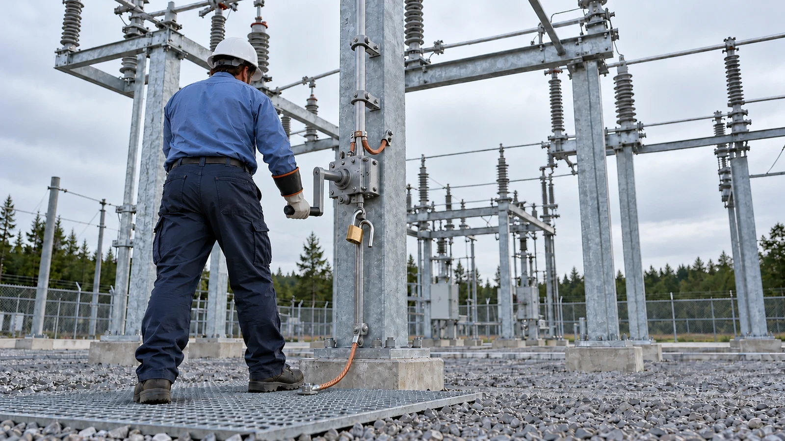
GOAB means gang-operated air break; utilities also use “group-operated.” In a three-phase installation, the common linkage moves the phase blades from one operating point. The arrangement can support visible isolation while keeping the operating handle away from the elevated contacts.
The linkage needs room. We check its route down the structure and the relationship between the operating handle and blade position. A vertical-break arrangement needs its upward travel envelope shown; a side-break arrangement needs the corresponding lateral space preserved.
A motor operator changes how the mechanism is driven. It can support remote commands when the control system is designed for them, but it does not turn a non-load-break disconnect into a load-break switch. The rating stays with the switch assembly.
For a powered arrangement, we specify the control-power interface and define local versus remote authority with the owner. Position indication needs review too. A command sent successfully cannot, by itself, prove that every blade reached the required position.
Load-break switches: match the interrupter to the duty
A load-break assembly provides a controlled means of interrupting specified current. The required duty must match the application, rather than relying on the continuous-current rating printed most prominently on the data sheet. Load interruption and continuous current are separate capabilities.
We identify any special duty for separate confirmation. Cable charging or transformer magnetizing current, for example, requires application-specific evidence; a general load-breaking description should not be stretched to cover every switching condition encountered on a distribution circuit.
Fault clearance remains a protection function. Our discussion of recloser design interfaces explains how equipment drawings depend on the utility's accepted protection requirements. We use the owner's supplied criteria without claiming to perform power-system studies or develop relay settings.
Bypass switches: preserve the intended maintenance path
A bypass establishes an alternate connection around equipment that the owner intends to remove from service. The bypass device still needs its own ratings. A drawing must also identify how the equipment being bypassed is isolated from possible supply on either side.
RUS Bulletin 1724E-300, Design Guide for Rural Substations, issued June 7, 2001 and still listed by USDA Rural Development, illustrates regulator and breaker/recloser bypass arrangements. It treats them as different applications. We use that distinction without importing a universal switching sequence.
Protection changes during bypass. The owner must establish which protective device remains effective when a breaker or recloser is bypassed. A regulator bypass requires its own operating conditions and equipment instructions. We show the accepted arrangement, while switching orders remain the utility's responsibility.
Pole-top line switches: design the feeder location
Outside the fence, a line switch can establish a sectionalizing point or a normally open connection between feeder sections. Its location should follow the owner's operating plan. The nearest convenient pole is not automatically the right switching point.
We coordinate the assembly with pole framing and conductor routing. The design must keep moving blades clear of nearby equipment and provide an accessible operating position, including space for the approved operating method when the switch uses a hook stick.
A pole-top location also changes the survey needs. Road access and the working area around the pole deserve explicit review before selecting the structure. A switch that fits electrically can still require a different pole or revised framing to become a workable installation.
Specify the Ratings and Frame the Installation Together
The equipment schedule and physical drawing should develop together. We use electric utility engineering for coordinated distribution designs to connect the operating requirement with the structure that must carry it. Purchasing a switch first leaves the layout to absorb decisions it did not make.
Write a rating schedule that distinguishes each duty
Voltage and insulation: Record the required rated maximum voltage and insulation level from the accepted design basis. Nominal feeder voltage alone leaves the specification incomplete. Environmental conditions can affect equipment selection and must be checked against the proposed assembly's application guidance.
Current ratings: State continuous-current capability separately from short-time withstand requirements. Where closing onto fault current is an assigned duty, identify the corresponding rating explicitly. We take the required values from utility-approved inputs and compare them with the equipment data.
Interrupting duty: Identify what the device must open under the owner's operating plan. The proposed interrupter and its mounting arrangement must support that duty. A substituted accessory needs review against the same requirement before the equipment schedule changes.
Site exposure: Confirm the applicable environmental and mechanical conditions. Ice accumulation can affect moving parts, and corrosive exposure can influence material selection. We require the supplier's application evidence for the project conditions rather than treating outdoor construction as proof of suitability everywhere.
Unresolved values stay unresolved. When an approved input is missing, we identify the decision that it blocks and return it to the responsible owner contact. A placeholder rating must not quietly become a procurement requirement because the drawing reached a new revision.
Show blade travel, support loads and access
A plan view needs an elevation. The closed position alone cannot establish clearances when a blade swings toward adjacent energized equipment, and the operating linkage may need space that is invisible in the one-line diagram.
We show the required movement envelope and coordinate terminal orientation with the connected conductors. Conductor forces at the terminals must be compatible with the equipment and its support, while the framing design accounts for the applicable structural loading conditions.
Grounding and operator access also meet at the mechanism. The grounding detail must coordinate the structure and operating components with the owner's accepted grounding design. A padlock on a handle does not address the electrical conditions at the operator's standing location.
Layout review: Ask operations to review the handle location while the drawing still shows surrounding equipment. A clear view of the switch and a usable approach can disappear when a cabinet is added later.
Our preference is to settle the operating envelope before completing the structure details. The limitation of that approach is its dependence on dependable equipment dimensions; a later substitution can reopen the framing and clearance review even when the headline ratings remain unchanged.
That review should include removal access. Equipment may fit in its installed position but require a different path for replacement, and an adjacent support can obstruct that path without appearing to violate the switch's normal operating envelope.
Carry the Switch Decision Through Drawing Review
The one-line establishes the electrical relationship. Physical drawings establish the installation. We reconcile their switch identifiers before release so the equipment schedule and field labels refer to the same device, with the same normal position and the same intended duty.
Review controls against the physical mechanism
Motor-operated installations require a defined interface between the mechanism and its controls. We document the owner's accepted interlocks and position indications in the control drawings. Local operation must remain consistent with the selected equipment's instructions and the utility's operating practices.
Loss of control power needs an answer. The design should identify what indication remains available and how the owner intends to manage the device under that condition. A communications point list should describe the installed capability rather than imply feedback that the mechanism cannot provide.
Keep design acceptance separate from field authorization
The owner reviews the package before procurement and construction proceed under its authority. Our distribution substation design and handoff guide places switch drawings within that wider review. Substation construction and field acceptance belong to the owner's crews or its contractor.
Draftech International's engineering is 100% in-house. Our distribution substation design service covers the design assignment; Draftech does not build, test, commission or energize substations. Approved utility inputs govern the drawings, and the utility retains operating authority.
For a replacement installation, existing records deserve field confirmation before details are reused. We need the actual mounting arrangement and equipment identification to judge compatibility. An earlier drawing can establish an investigation starting point, but the proposed replacement must match the verified installation.
Choose the Next Step by Your Operating Need
Utility substation engineers: Establish the isolation boundary and required interrupting duty before selecting the assembly. Then require the physical drawing to show the complete blade envelope. This keeps an acceptable electrical rating from concealing an unworkable arrangement.
Co-op distribution teams: Select pole-top locations from the accepted feeder operating plan. Review access with operations before completing framing, and distinguish a planned isolation point from a point that must open load during the intended switching duty.
Procurement reviewers: Evaluate substitutions against the specified duty and the approved mounting dimensions. Return a proposal that changes either without supporting application evidence. Matching the continuous-current rating alone leaves too much of the design unchecked.
Draftech International provides turnkey telecom and power infrastructure, with full turnkey distribution and make-ready construction delivered by Draftech-managed subcontract crews. Substations remain design only. Our partner and company information identifies the accountable team. Active in 24 states. Available across all 50 U.S. states.
If the switch duty or operating clearance is still unsettled, send the accepted one-line and available equipment data through our project contact page or email info@draftech.com. We can scope the design work around those open decisions before they become incompatible purchase requirements.
For a qualifying route associated with your broader infrastructure program, the free design offer provides engineering for the first 20,000 linear feet at no cost, from feasibility and field survey through permit approval. The owner reviews each request before Draftech commits the package.