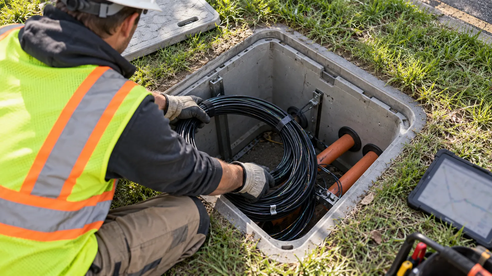
A fiber route can look buildable on a plan while leaving no practical place to open a splice closure. We treat the access enclosure as part of the cable system, because its location determines whether the next technician can reach the equipment and work without disturbing neighboring fibers.
This guide follows the enclosure decision from its purpose to its installed position. We compare access functions and load classes, then explain how cable handling constrains the available space. The aim is a box that supports installation and remains usable when the network needs maintenance.
What a handhole does in an underground fiber network
A handhole is a below-grade access enclosure that lets technicians reach underground fiber cable from the surface. It can hold slack loops and splice closures or provide a pulling point. ANSI/SCTE 77 tiers such as Tier 8 describe enclosure loading; selecting the box also requires usable interior dimensions and a suitable location.
At the opening, we need enough room for a technician to remove the cover, identify the correct cable and retrieve the intended closure without forcing an adjacent live cable into a tighter bend. The lid must then close without bearing on the stored assembly, which further limits the space available for cable. A rectangular symbol on a route drawing conceals those physical constraints unless the design includes an interior arrangement.
Handhole versus vault
A handhole normally supports work performed from above, while a vault provides a larger underground chamber for equipment or more extensive cable arrangements. Terminology varies between owners. We specify the access method and clear dimensions rather than treating either name as a complete design requirement, especially when a drawing calls a deep structure a handhole but expects a person to enter it.
When the work requires entry, a larger chamber needs its own evaluation for confined-space hazards and access procedures. We establish whether entry is permitted through that assessment, regardless of what the structure is called. For existing structures, we need measured duct positions and usable space before deciding whether the new cable fits. Our vault and manhole survey guidance explains the field records needed to support that decision.
Pull box describes a function
Because a handhole can provide access during cable installation, the same structure may also be described as a pull box. A pull-through location may carry an uninterrupted cable with no splice, while a branching location may require a closure and enough recoverable slack to bring it to the work area. We label the function explicitly so procurement does not substitute a small pulling enclosure for a splice location.
From the network diagram, we establish which fibers branch at the access point and what the enclosure must accommodate to support that architecture. When a distribution hub feeds several downstream routes, enclosure requirements depend on the feeder and distribution arrangements established during fiber distribution hub sizing for FTTH and PON. We keep the splice assignment tied to the enclosure schedule so a revised hub layout triggers a review of the affected boxes.
Select the handhole load rating from its location
To assess loading, we begin with the surface around the cover and the activity it supports. Grass beside a road can be exposed to a turning vehicle, and a paved walkway can also serve maintenance equipment. Our review considers how the area is used and what can reach the box, since the surface label alone tells us little about vehicle exposure. We also check the permit detail, which may require a higher class than the initial route design anticipated.
Use the standard within its scope
ANSI/SCTE 77-2023, Specification for Underground Enclosure Integrity, is the current SCTE catalog edition. It addresses grade-level enclosure performance in non-deliberate traffic areas. SCTE directs deliberate traffic applications to AASHTO requirements. Tier 22 therefore cannot be treated as blanket approval for a travel lane or a routinely crossed driveway; that location needs the governing authority's traffic-loading criteria and an enclosure assembly accepted for them.
During submittal review, we distinguish the design load from the higher qualification test load. The latter demonstrates performance under the prescribed test conditions; it does not become an operating allowance. A tier number also does not describe vehicle gross weight. For the complete assembly to meet the specified rating, the box and cover must be compatible and the submittal must document that combination rather than an isolated replacement lid.
Location selection precedes the material order because moving a box across a curb can change its exposure without changing the cable route very much. Our drawing review asks whether wheels can reach the cover during ordinary use and whether unusual access is still foreseeable. A protected verge and a paved turning path deserve different decisions even when they share the same plan-sheet symbol.
| Location being evaluated | Selection basis | Vertical design / test load | Design decision |
|---|---|---|---|
| Protected sidewalk or similar non-roadway area | Tier 8 where accepted | 8,000 / 12,000 lb | Check incidental vehicle exposure and owner requirements. |
| Off-roadway area with occasional non-deliberate vehicle loading | Tier 15 where accepted | 15,000 / 22,500 lb | Confirm the assembly matches the specified exposure. |
| Off-roadway area requiring greater incidental-load capacity | Tier 22 where accepted | 22,500 / 33,750 lb | Confirm supporting installation and assembly documentation. |
| Travel lane or other deliberate vehicle path | Authority-approved traffic-rated design | Project-specific | Relocate the box or obtain an accepted traffic design. |
Apply Tier 8, Tier 15 and Tier 22 deliberately
Tier 8 is a candidate for suitable sidewalk or protected off-roadway locations where the owner accepts that loading class. Before selecting it, we verify access: a walkway that doubles as a service-vehicle route needs an exposure assessment that accounts for those vehicles as well as pedestrians. A cover surface also needs to suit the walking route and the applicable accessibility requirements.
Tier 15 and Tier 22 address higher loads in the non-deliberate traffic category, with the latter carrying the higher design load shown in the table. For the site under review, we document why a heavier class is needed and check that selection against the owner's approved details. Neither rating resolves a location where vehicles are expected to cross the cover as part of normal circulation.
Check the replacement lid: Keep the approved box-and-cover assembly identification in the asset record. A lid that fits the opening can still lack the documented compatibility needed to preserve the specified rating.
Size the interior for slack and splice access
To determine how much cable an enclosure can store, we check clear space at the elevation where the cable will sit; nominal outside dimensions can hide tapered walls or a reduced opening. The closure must pass through the opening with its attached cables supported. A larger footprint may help more than additional depth when a wide slack loop or a long closure drives the arrangement.
Start with the cable limits
The Fiber Optic Association's Outside Plant Construction Guide distinguishes bending limits during installation from those after the pull. Use the selected cable's published limits for both conditions. We also retain the specified maximum pulling tension in the design package so the route geometry and installation method are checked against the same cable, rather than against a generic fiber diameter.
When translating the cable's required bend radius into a storage footprint, we allow a circular loop diameter of at least 2 times that radius, then account for cable thickness and any supports. That geometric relationship is only a starting check: an enclosure corner or duct entry can create a tighter local bend even when the broad coil appears to fit comfortably inside the box.
Reserve working space around the closure
A closure drawing shows its body, but the installed assembly also needs room for cable entry and strain relief. Our review covers both the closed storage position and the movement needed to retrieve the closure. Following that movement through the proposed layout lets us check whether a technician can lift the intended assembly without dragging another closure across its cable tails or taking apart unrelated live storage.
For maintenance, the cable must reach the intended splicing position with sufficient reserve for the owner's repair method. That working distance helps determine slack length, while the storage arrangement must allow the loop to return to the enclosure without twisting. We assign the reserve to the cable segment that needs it. A total footage note can conceal a shortage on one side of a splice if the other side holds most of the reserve.
One limitation of our preference for additional working space is that a larger enclosure can require a location that the available right-of-way cannot accommodate. We resolve that conflict before issuing the plan. The answer can be a revised closure arrangement or a different access location, provided the revised arrangement still supports the required cable handling and maintenance access.
The records should show occupied duct entries and space reserved for planned expansion clearly enough for us to check whether adding cable would block the retrieval path for existing closures. We coordinate those decisions through our FTTH design work, where the splice schedule and physical layout are reviewed together. Before counting an empty corner as future capacity, we need to see how the additional cable would sit there and how existing closures would remain accessible.
Set spacing from the installation and maintenance plan
The Fiber Optic Association's Fiber FAQs ties handhole spacing to cable installation constraints and route bends, so the distance between access points emerges from the route design rather than a universal interval. We begin with required network access locations and test the intervening installation sections. Equal spacing may be convenient for drafting, but the cable experiences the actual duct geometry.
Check the difficult pull section
A short section with several bends can be harder to install than a longer straight section because tension builds through the route and bends concentrate contact forces. We evaluate pull direction and the proposed cable against the duct alignment and installation method, including where equipment can stand. The access point must give the installation crew a usable setup area outside the opening.
Changing a pulling point changes more than the distance printed beside the route. It can alter the approach angle at a duct mouth and the length available for handling cable above ground. We ask the installation planner to confirm the revised setup before accepting a relocation. A geometrically convenient box becomes a poor access point when the planned cable handling occupies an unavailable parcel.
Distinguish access points from splice points
An intermediate opening can support a continuous cable installation without introducing a splice, and the drawing needs to make that intended function clear. We coordinate access locations with reel allocation and the approved handling method, reserving splices for the network and maintenance requirements that justify them. Otherwise a drawing revision can quietly turn a pulling aid into an additional splice that was never carried in the optical design.
Air-assisted installation requires a different set of checks from a conventional pull. The proposed equipment and cable-to-duct combination influence achievable sections, while access remains necessary wherever the approved installation plan needs it. We require the method to be stated before treating a long uninterrupted run as buildable. A distance achieved with another cable cannot establish the spacing for this route.
Review relocations as design changes: When a proposed box moves, check the adjacent installation sections and the closure retrieval area together. A revised coordinate alone leaves the cable-handling assumptions unresolved.
Place the box within a usable right-of-way
Within a right-of-way boundary, the space available for a new enclosure still needs to be established. Existing utilities and surface uses can remove the space a plan appears to offer. Before settling on a footprint, we confirm the right to install and maintain the enclosure and use field measurements to establish where it can fit. Even an opening inside the boundary may need a separate accommodation decision before we can proceed.
Coordinate clearances and surface use
Required offsets come from the applicable authority and utility-owner criteria. We put those project-specific dimensions on the drawing instead of publishing a universal curb setback or separation distance. The same review needs to cover the excavation footprint, because an enclosure that clears a utility after installation can still require an excavation or support method that conflicts with the neighboring facility during construction.
Pedestrian routes need usable passage during maintenance, including room around an open cover. At driveways, assess the actual wheel path and turning movement rather than the edge of pavement alone. We also examine access from a parked work vehicle. If technicians must work from the travel lane to reach a box described as off-roadway, the maintenance arrangement needs further coordination.
Account for water and finished grade
A section detail helps us evaluate drainage where a low point can collect runoff or groundwater can enter an enclosure even when the surface sheds water. We specify cable and closure suitability for the expected environment and coordinate any drainage provisions with the approved installation detail. Adding aggregate beneath a box does not guarantee that standing water will disappear in poorly draining ground.
Finished elevation must work with the surrounding surface and the approved detail. We check whether restoration will leave a trip edge or direct runoff toward the opening, and whether nearby grading could bury the lid later. We document the elevation reference so the field crew has a recoverable control point when other work has already disturbed the original ground surface.
Requirements vary by service area, which is why our service-area coverage is a starting point for project coordination rather than a substitute for an authority's detail. Active in 24 states. Available across all 50 U.S. states. We confirm the responsible authority and utility owners for the actual route before applying a standard enclosure note across an entire plan set.
Choose the enclosure package your team can maintain
For a network designer: Fix the closure arrangement before finalizing the enclosure schedule. Show the usable interior and cable entry geometry so the specified box can be evaluated against the intended splice work. Maintain that connection to the optical plan by reviewing the storage drawing whenever a closure changes, checking whether the original enclosure still accommodates the new assembly.
For an owner expanding existing plant: Measure what is inside the structure before assigning another cable to it. We favor a recorded retrieval check over a visual estimate of spare volume, because a vacant space may be the only path available to remove an existing closure. Where expansion would obstruct that maintenance access, a separate enclosure can be the better choice for preserving the retrieval path.
For a construction manager: Verify the approved assembly at receipt and inspect its support before backfill conceals the installation. Record the final cable arrangement with the cover open, then verify closure access and cover seating. We carry deviations back into engineering review before they become accepted records. Photographs should let the owner identify the enclosure and understand how its contents were left.
Our acceptance record ties the installed asset identifier to its final location. It should also retain the approved assembly reference and the cable storage arrangement, with any relocation carried into the as-built drawing. During inspection, we pay particular attention to the support and duct entry, since the top of a lid will reveal little about that hidden work once the surrounding surface is restored.
Draftech International delivers turnkey telecom and power infrastructure, from field survey and planning through construction drawings, permits, agency coordination, construction, as-builts and closeout. Our engineering is 100% in-house. Full turnkey construction is delivered by Draftech-managed subcontract crews under Draftech's QA/QC and safety program. Our partner responsibilities identify the people accountable for carrying that delivery model through the work.
Cramped closure storage and inaccessible lids begin as design decisions, so we connect the enclosure schedule to field conditions before construction. Bring the proposed route and the owner's enclosure requirements to our project coordination team; we can assess what the design package must resolve. For a specific technical question, write to info@draftech.com with the affected route segment and enclosure detail.
For a qualifying route, Draftech engineers the first 20,000 linear feet at no cost, from feasibility and field survey through permit approval. The owner reviews each request before Draftech commits the package. Our free design offer gives you a way to bring the access locations and route constraints into that review while the engineering decisions are still open.