In This Article
A test folder arrives with a green summary page, but the inspector cannot match its fiber labels to the splice schedule. Acceptance stops there. The owner needs evidence tied to the installed plant, and the testing contractor needs a clear way to show which records support release.
We use the described sample below to explain that handoff for ISPs, co-ops and inspectors. It contains no real project data or fabricated readings. Its fields show where measurements belong, how to review them and what we would carry into the as-built package before requesting acceptance.
What a fiber optic test report sample must show
A fiber optic test report sample shows how measured performance connects to an identified installed link and its acceptance requirements. Our example groups the evidence into 6 report sections, covering project identity, fiber mapping, OTDR records, insertion loss, test equipment and acceptance disposition, without presenting invented measurements as completed work.
Start with the tested boundary. The report should state where the measurement begins and ends, including whether it covers a cable segment, a terminated link or a path through passive components. Those boundaries determine which losses belong in the result. We would return a report that leaves them ambiguous.
Consider an illustrative link between an origin panel and a destination panel, with intermediate splice closures shown on the accepted drawing. The sample names these endpoints by role only. In an actual submission, the owner would replace those descriptions with asset identifiers that match the field labels and the controlled drawing revision.
Read the cover before the results
The cover identifies the project or work package and the report revision. It also names the submitting organization and the person responsible for review. We want the test date beside the acquisition records, because a newly exported PDF can contain measurements taken before the final splice configuration existed.
To distinguish when the test happened from when someone issued or accepted the report, record acquisition, report issue and owner disposition separately. Include the time zone when timestamps matter to the sequence of work. If a repaired fiber was retested, a reviewer should be able to establish which measurement followed that repair without interpreting a file's download date.
Before reviewing individual results, we look for a scope statement identifying the included fiber population and any excluded fibers. A spare strand can still belong in the acceptance scope. An exclusion needs the owner's documented basis, especially when the contract requires testing every installed fiber and the submitted summary covers only assigned service paths.
Make the fiber identity survive every export
The link ID is the joining field. Carry it through the summary and the native measurement files, then connect it to the cable record in the drawings or GIS. We also expect the fiber designation at each end, since a continuous optical path can cross different cable and fiber numbers.
To identify a strand beyond its color, the sample reserves fields for the cable identifier and the fiber designation within that cable. Panel and port references identify the terminations. Where the path changes fiber assignment at a splice, the splice schedule should explain the transition rather than forcing an inspector to infer it from matching colors.
When the instrument moves to the opposite end, its display reverses the distance axis. Keep the original origin and destination labels throughout the report so that this change does not also change the meaning of the recorded direction. Our review would check the endpoint pair before comparing any event, because a correctly measured neighboring fiber cannot establish this link's performance.
The sample also identifies fiber type and the test wavelengths required by the approved procedure. It leaves the measured length empty until acquisition. A planned route distance should never be copied into that measurement field merely to make the report appear complete; the two values answer different questions.
Fiber optic test report sample outline
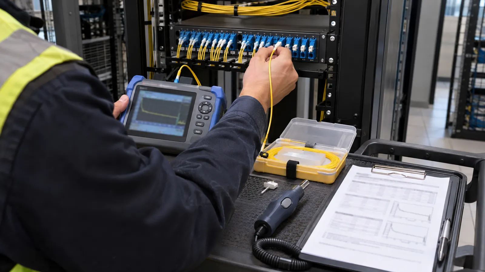
Each row in this outline describes a report section and the evidence an inspector should expect behind it, using words instead of readings. In our suggested PDF order, someone reviewing an exception can move from the summary to the relevant acquisition without searching through unrelated traces.
Because page order can change in a merged PDF, assign every attachment a report reference that survives export. The reviewer can then request clarification about a particular trace without relying on its position in the file.
| Report section | Sample contents | Review purpose |
|---|---|---|
| Cover and scope | Work package, revision, test boundary and included fibers | Establish what the submission covers |
| Link identification | Cable and fiber IDs with endpoint panel and port references | Match results to installed assets |
| OTDR evidence | Native traces, event tables and paired directional records | Review individual events and measured length |
| Insertion loss | Reference method, wavelength results and approved loss budget | Compare measured end-to-end loss with the allowance |
| Equipment and method | Instrument identifiers, calibration evidence and acquisition settings | Establish measurement traceability |
| Acceptance and closeout | Disposition, exceptions, retest references and drawing revision | Record the owner's release decision |
A blank sample should remain visibly incomplete. Use a clear missing-data label for an unavailable required reading, and distinguish that condition from a field that does not apply to the approved method. Neither should silently become a pass when the report software generates its summary.
Keep a summary and the supporting files
For review, we would provide a readable PDF; for technical examination, the native files. Index both by the same identifiers. A screenshot can show a curve but omit settings needed to interpret it. Retain the original acquisitions, and identify any analysis changes that affect the exported event table or its pass/fail classification.
The file index should identify the current accepted candidate for each required test. Preserve earlier failures as history. If both versions sit in the same folder without a clear disposition, the operations team can mistake a superseded result for the baseline when investigating a later fault.
Review the OTDR traces and event tables together
The OTDR section contains the trace for each required wavelength and direction, with its acquisition settings attached. Its event table should list measured event distance and event type, then loss and reflectance where the event and method support those measurements. We review the plotted trace beside the automatic classification.
Separate splice loss, connector loss and reflectance
A splice event's loss describes the change associated with that location; connector loss describes a mated connection in the test path. Reflectance concerns returned light at an event. Keep these fields separate. A value expressed in dB still needs its quantity label, and reflectance should not be confused with whole-link optical return loss.
Our sample reserves a place for launch and receive fiber details so the reviewer can establish which terminal connections were visible in the acquisition. Where events remain unresolved, check the spacing between connections: a short spacing can prevent the trace from distinguishing them separately, depending on the selected pulse and the instrument's dead-zone performance.
For the curve itself, our guide to reading an OTDR trace explains how event shape and dead zones affect interpretation. Here, the acceptance question is whether the report contains enough information to support that interpretation. We would request clarification when a clean event table is unsupported by a usable trace.
Before comparing length against the drawings, check the instrument's refractive-index setting and the defined test endpoints, since both affect the reported optical distance. Route drawings describe installed geography, while cable slack and routing inside structures affect the relationship. An unexplained mismatch calls for investigation. Do not force the drawing footage and the OTDR result to agree by editing a measurement.
Show bidirectional averaging without hiding either direction
ITU-T G.650.3 describes bidirectional OTDR analysis for installed single-mode links. Differences in backscatter characteristics across a splice can make its apparent loss depend on test direction, including an apparent gain. Pairing measurements of the same event from opposite ends helps estimate splice loss without treating that gain as generated optical power.
Once the physical event is matched, show the A-to-B reading, the B-to-A reading and their arithmetic average in dB, under the approved procedure. Our sample leaves all of those readings unfilled. The paired records need the same wavelength and a defensible event match, even though the distance from each test origin differs.
Use averaging to evaluate the matched splice. Combining different wavelengths, unrelated events or different fibers into a favorable result falls outside that purpose. With the directional traces beside the calculation, we can inspect an apparent gainer and determine whether the event pairing is valid.
Match from both ends: Before accepting an averaged splice result, locate the same physical event in the reverse trace. A repeated event number from an automatic table is insufficient evidence of a match.
Compare insertion loss with the approved loss budget
The insertion-loss section records a measurement made with a light source and power meter. An optical loss test set (OLTS) supplies that measurement capability. The Fiber Optic Association's Reference Guide, Testing the Installed Fiber Optic Cable Plant With a Test Source and Power Meter, explains the reference measurement and comparison with a calculated loss budget.
State the reference method and included connections
The report should identify the reference method and the test cords used, then state the wavelength and test direction for each required result. The reference setup affects which connections are included. We would ask for that setup to be clarified before accepting a comparison between results acquired under different reference conditions.
Include the reference check in the acquisition record, identifying which measurements followed a new reference when the procedure requires one after a setup change. A result exported as a small loss does not explain whether the reference was suitable, whether the test connections were clean or whether the intended link was measured.
Beside each result, show the approved allowance for the defined link and the basis used to establish it, including applicable fiber attenuation and component allowances. Distinguish this installation acceptance budget from the active equipment's optical power budget, which can include operating reserves beyond the installed cable's measured loss.
Separate result rows let us review each required wavelength and direction against its applicable limit, with the disposition visible. Do not average insertion-loss results to erase an individual failure unless the governing procedure expressly defines that treatment. OTDR event averaging and OLTS acceptance are different review tasks.
Name the applicable standards precisely
TIA-568 is a family of cabling standards; the report should identify the applicable document and edition rather than citing the family name as a complete test instruction. TIA-526-7 addresses installed single-mode optical power loss measurement. TIA-526-14 addresses installed multimode optical power loss measurement, so fiber type determines which procedure is relevant.
IEC 61280-4-1 addresses installed multimode attenuation measurement, and IEC 61280-4-2 addresses installed single-mode attenuation and optical return loss measurement. Their presence in a specification does not mean every report must contain every possible test. We would record the adopted edition and the owner's required scope before deciding which fields are mandatory.
For a closer look at the basis of those limits, our discussion of OTDR acceptance criteria and splice loss explains why the contract's event limits and link requirements must govern the pass/fail decision. The sample therefore provides a limit-source field instead of printing a universal splice allowance that could be wrong for the job.
Preserve the original decision basis: If a limit changes during review, retain the prior criterion and document the authorized replacement. Re-exporting a green summary alone does not explain why the same measurement now passes.
Carry equipment evidence into the as-built package
The equipment section identifies the individual instruments and applicable modules by serial number, with calibration evidence covering the acquisition date. Our equipment record would also retain relevant firmware or analysis-software versions. Those details let a reviewer distinguish a change in measurement from a change in how the report software interprets the file.
Check calibration and acquisition settings
When the contract requires a calibration certificate or record, a handwritten statement that equipment was calibrated cannot take its place. Check the recorded calibration date and applicable due date, and investigate any gap against the required interval rather than assuming every instrument follows the same calendar.
The tester field should identify the person who performed the acquisition and the organization responsible for the test. Keep that role separate from the inspector and accepting authority. Where witness testing is required, record who witnessed it and which acquisitions were observed instead of attaching a general signature to an undefined population.
Retain OTDR pulse width and range with the other acquisition parameters, including averaging duration and the refractive-index setting. For OLTS, preserve the reference setup and the required source conditions. These settings establish how the result was obtained; they should travel with the data even when the summary page omits them for readability.
Reconcile the final installed configuration
Test timing should follow the approved construction and acceptance sequence, with affected results revisited after changes to the tested path, as discussed in our FTTH testing guide. A passing pre-repair measurement cannot document a different final connection. We want the report revision to identify the installed configuration it supports.
Stable asset IDs give us a way to join the accepted test index to the splice schedule and drawing revision. That connection is part of our as-built documentation handoff: someone starting from a panel port should be able to locate its test record and follow the fiber path through the installed network.
The PDF alone has a limitation: it cannot prove that the labels in its header match the physical ports in the field. Our preferred package therefore includes the applicable field verification records alongside the test index. Good document organization helps expose a mismatch, but it cannot replace missing physical identification.
To keep exceptions visible through closeout, record each unresolved issue and its affected assets, with the responsible party and required corrective action attached. After correction, retain the new acquisition and the review disposition. Acceptance should state whether the owner released the whole scope or only a defined portion.
Our release recommendation for owners and inspectors
For ISPs and co-ops: require an asset-linked test index before accepting the package. During our review, we would reconcile that index against the required fiber population, then confirm that the operations team can open the native files and locate the accepted baseline without depending on the submitting contractor's folder habits.
For inspectors: review the measurement method before trusting the pass flag. Check the applicable limits and examine exceptions against their supporting acquisitions. An unresolved identity mismatch warrants a return for clarification, even when every displayed value sits inside the programmed limits.
For construction managers: carry each correction through to the closeout revision. Before releasing the affected work, we would assign responsibility for that update: repaired plant and unchanged documentation leave the owner with conflicting evidence. Use our contact page to discuss the required handoff when defining that responsibility.
Draftech International delivers turnkey telecom and power infrastructure, from field survey and planning through construction drawings, permits and agency coordination to construction, as-builts and closeout. Our engineering is 100% in-house. Full turnkey construction is delivered by Draftech-managed subcontract crews under Draftech's QA/QC; our company overview explains the team's responsibilities.
For a fiber package with disconnected test records, our fiber splicing and testing service provides OTDR and insertion loss testing. We focus the handoff on identified fibers and reviewable results so the acceptance decision has a clear basis. Discuss your required report format with us at info@draftech.com.
On a qualifying route still entering design, Draftech engineers the first 20,000 linear feet at no cost, from feasibility and field survey through permit approval, through our free design offer. The owner reviews each request before Draftech commits the package. That early scope definition gives the future testing and closeout requirements a place in the route's design decisions.