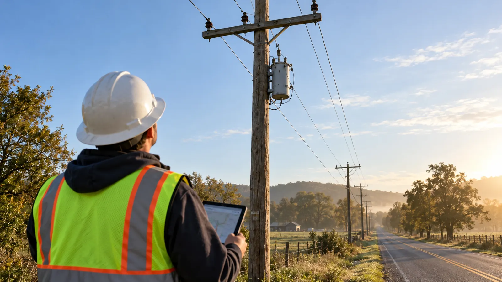
A new building can sit beside an electric line without having the supply arrangement it needs. To find out what that line can serve, we start with the connected equipment and the utility's approved configuration. From there, the review extends to the route and the property it crosses.
What the distribution grid carries from substation to meter
The distribution grid is the electric system that carries power from distribution substations through primary feeders and local transformers to customer meters. Primary circuits commonly span roughly 4 to 35 kV, while transformers reduce voltage for customer service. Its physical layout determines which equipment serves each customer and where outages can be isolated.
A feeder drawing becomes useful when we can follow an actual service connection back to its source. Starting at the meter, trace the secondary conductors to the transformer and follow its primary connection to the lateral. Continue toward the feeder breaker at the distribution substation. That path reveals which assets a proposed extension depends on, even when those assets sit outside the developer's property.
Distribution substations and outgoing feeders
A distribution substation establishes the feeder supply voltage and provides the bus connections from which outgoing circuits depart. Breakers and associated controls divide those circuits into operating boundaries. We keep the substation interface explicit on project drawings because an outgoing cable route can be buildable while its termination location remains unresolved. If the work requires access through the station fence, that access belongs in the owner's approved scope.
A primary feeder is the main distribution circuit serving an area; laterals branch from it toward smaller groups of customers. A main feeder commonly carries three phases, while a lateral may use fewer where the connected load and utility design allow. Our route review identifies the phase arrangement at the proposed connection rather than assuming every wire visible on a pole belongs to the same circuit.
For a development that combines homes with commercial premises, demand may peak at different times across the site. The service request therefore needs to describe the load; a building count alone cannot establish the equipment required. We ask the utility to confirm its supply arrangement before a site plan fixes transformer locations. That decision belongs in the civil drawings, since moving equipment afterward can disturb access rights and service routes already agreed with the owner.
Primary voltage ranges and equipment ratings
For orientation, typical nominal primary voltages fall into bands around 4 to 5 kV, 12 to 15 kV, 23 to 25 kV and 33 to 35 kV. The Department of Energy's Electricity Distribution System Baseline Report, PNNL-25178, identifies representative values of 4.8, 12.47, 22.9 and 34.5 kV. These are reference bands, not a continuous menu from which a developer chooses a supply voltage.
When we read nameplates against construction standards, the voltage convention matters. USDA RUS Bulletin 1728F-800 identifies distribution construction at 12.47/7.2 kV, 24.9/14.4 kV and 34.5/19.9 kV, with paired values distinguishing phase-to-phase and phase-to-neutral voltage. Our equipment records preserve that distinction and identify the equipment voltage class separately from the circuit's nominal operating voltage. Matching a rounded number without checking the utility's required insulation rating can produce the wrong specification.
Transformers, secondaries and the service point
Distribution transformers reduce primary voltage to the secondary voltage required for customer service. They may be mounted on poles or installed in pad-mounted enclosures, with vault installations used where the utility's arrangement calls for them. The DOE baseline report identifies 120/240 V residential service as a common example. The utility determines the available service configuration; a customer's equipment requirements must match that confirmed supply.
The secondary runs between the transformer and the service connection, sometimes serving several customers from shared conductors. To make ownership clear, we show the utility's service point and the customer-owned work on the same drawing. Responsibility is assigned at that boundary rather than inferred from the meter location. A meter measures delivered energy; it does not, by itself, establish ownership of every adjacent conductor or enclosure.
Transformer access deserves space on the civil plan because a cabinet that fits between parking spaces may still conflict with the utility's working area or replacement access. Landscaping can also obstruct doors that opened freely at installation. Alongside the owner's clearance requirements, our drawings coordinate finished grade with the equipment foundation. A drainage change must not leave operating access below the surrounding surface.
How distribution layouts change the available supply paths
Switch positions determine whether a route drawn as a loop operates radially. We read the geographic plan beside the electrical one-line so that a line drawn between adjacent circuits is not mistaken for a connection normally carrying power. The comparison below separates construction form from operating arrangement; an underground circuit can use any of the layouts its owner has designed and approved.
| Arrangement | Normal supply path | Design implication |
|---|---|---|
| Radial | One source path to the section | Identify every customer downstream of the work. |
| Normally open loop | Radial operation with an alternate physical path | Confirm the open point and permitted transfer arrangement. |
| Secondary network | Interconnected secondary supplied by multiple transformers | Use the owner's network-specific service requirements. |
| Hybrid overhead and underground | Determined by switching, not burial | Coordinate risers and access at construction transitions. |
Radial circuits and normally open loops
A radial circuit has one normal supply path to a customer or section. That arrangement makes the source path straightforward to identify, but an interruption upstream can affect every customer downstream until operators isolate the problem or establish an approved alternate feed. When we identify the affected branch on the design, we also check its supply path. Extending a radial lateral still leaves it dependent on the same path past a damaged span.
With a loop, the physical path runs around an area, often with an open point that preserves radial operation during normal service. Operators may isolate a damaged section and supply healthy sections from the other direction where the system permits. Before relying on that alternate path, the owner needs to confirm its available capacity and approved equipment arrangement; drawing a complete loop on a presentation plan cannot establish either.
Our preferred starting point for loop planning is the owner's normal-open-point record. Its limitation is that a drawing can become stale after field switching, so the utility must confirm the operating arrangement before it becomes a design assumption. On our drawings, the planned final configuration is distinguished from any temporary construction state, so an intended future tie cannot be mistaken for an available supply today.
Networked layouts and construction form
A secondary network connects customer loads to interconnected low-voltage conductors supplied through multiple network transformers, with specialized protection at the transformer connections. A spot network concentrates that arrangement at a particular facility or load. Identifying this topology early tells us which service requirements to use. A change in a network area must follow the owner's network requirements rather than details borrowed from a radial residential service package.
Overhead distribution places conductors on structures where crews can inspect much of the route from the surface. Underground construction places cable below grade but still needs accessible equipment locations. Either construction method can accommodate different topologies. Where a hybrid feeder runs overhead along a road and enters an underground development through risers, those transition structures become important interfaces for the entire route.
For an existing corridor, we treat overhead-to-underground conversion planning as a separate design task because removing poles changes service connections and can affect other attachments. Burial also changes how crews reach damaged equipment: they need room along the route to locate faults and replace cable. We account for that access before development fills the surrounding property, so equipment remains reachable.
What feeder protection and switching devices do
Four device families explain much of what a reader sees along a feeder: fuses, reclosers, sectionalizers and switches. Devices that look similar from a distance can have different operating capabilities. For that reason, we use the asset record to identify each device's type and rating. A switch symbol alone cannot tell the reviewer whether a device can interrupt fault current.
Fuses and reclosers
A fuse clears an overcurrent condition by melting its element according to its characteristic. The operated element needs replacement before that fused path can return to service. Its application depends on the utility's protection requirements and the equipment being protected. In our drawings, the specified fuse location distinguishes lateral protection from transformer protection. They occupy different positions in the circuit, even if both are described casually as the fuse on the pole.
A recloser can interrupt fault current and automatically attempt to restore the circuit under its configured sequence. A temporary fault may clear before a subsequent closing attempt, allowing the healthy circuit to remain energized. Persistent faults lead to lockout under the approved controls. Because the utility decides how to use reclosing, it retains settings and switching authority. We carry its approved requirements into the physical installation package.
Sectionalizers and switches
A conventional sectionalizer works with an upstream interrupting device and opens during a de-energized interval to isolate a section. It does not perform the same fault-interruption duty as a recloser. Eaton's TVS sectionalizer instructions, S270-30-1, illustrate coordinated operation with an upstream recloser. With designs varying between devices, the supplied equipment and its approved control sequence must match the function assigned on the utility's drawing.
Switches provide connections or isolation points, with capabilities that depend on their construction and ratings. A loadbreak switch can interrupt its rated load current; that label does not establish fault-interrupting capability. EPRI's Distribution Switching Devices Application Guide, report 3002012898, distinguishes switching duties when specifying automation devices. We require the equipment designation to remain visible through procurement so a substitution does not silently change the intended function.
Identify the normally open device on both the one-line and the location plan. Use the owner's equipment identifier on each, so the field location can be matched to the intended operating boundary without guessing from a nearby road name.
Installing protection devices also means accommodating their physical support and access requirements. Mounting a new recloser can affect a pole's arrangement, while a ground-mounted switch needs a working area that survives later paving or fence installation. Our electric distribution engineering and construction services connect those installation details with field survey and owner standards. The utility retains control of energization and operation; our package must clearly define the construction work it has accepted.
How utilities choose distribution grid upgrades
An upgrade starts with the reason a feeder needs work. Additional demand may call for capacity, while repeated tree-related damage points toward a different intervention. We separate those needs before recommending a route treatment. The Department of Energy's Integrated Distribution System Planning guidance ties investment choices to owner objectives and functional requirements, a useful discipline when several proposed projects compete for attention on the same feeder.
Capacity and asset condition
Capacity work must address the limiting part of the supply path. A larger transformer at the customer end may leave an upstream conductor constraint unchanged, while a new feeder segment may require corresponding changes at its source connection. Using the accepted planning basis we request from the owner, the design team identifies which facilities need alteration and which existing equipment remains suitable for the intended service.
Field condition can change the project boundary when, for example, a pole replacement identified during route survey affects adjacent spans. Where the existing arrangement includes communications attachments, those attachments must move before the old structure comes out. Our work package records that dependency and distinguishes replacement for condition from changes needed to support growth. The owner can then track why each asset is included and which adjacent work its replacement depends on.
Hardening and selective undergrounding
The failure mechanism guides the choice of hardening work. Stronger structures address different exposure from vegetation work; where flooding threatens equipment, relocating it addresses another problem. Our distribution storm-hardening design guide explains how to compare feeder consequences with the hazards affecting each segment. For each proposed treatment, we identify the asset it protects and the failure it is intended to reduce.
Selective undergrounding can remove exposure to falling branches on the converted segment, but the circuit still depends on its remaining overhead supply and accessible equipment. To account for water exposure, we examine surface drainage around aboveground cabinets and the owner's provisions for belowgrade structures. Because buried plant still needs protection from weather, we use the conversion boundary to distinguish the exposure removed by the work from the exposure that still affects service.
Reserve equipment access when the route is selected. A pad location that later becomes a fenced storage area can defeat an otherwise workable underground design, so carry the operating space into the property agreement and the final site plan.
Automation and the fiber that connects field devices
Automation adds sensing and remote operation to selected field devices. Some schemes use utility fiber; others use radio or a different communications path approved by the owner. Before reserving a cable route, we ask what the device must exchange and where that connection terminates. Even with an available strand beside the feeder, a working connection to the control equipment still has to be established.
The physical communications design follows the electrical device locations. A pole-mounted control requires a defined cable entrance and termination arrangement, while a cabinet needs a protected path from the outside fiber to the communications equipment. Our design carries those interfaces through to the equipment connections. If the intended function must remain available during an interruption of normal supply, power for the controls and communications equipment also needs an owner-approved arrangement.
To check route diversity, we trace the physical paths because separate fibers in the same cable share its exposure. Even separate cables can be lost together if they occupy the same pole line. The owner can then decide whether the proposed communications arrangement supports the intended operating function or needs a different route, without assuming that additional strands create independent paths.
Our records preserve what was installed: we connect the final device identifier to its location and carry the fiber termination information into closeout. Field changes must be resolved before the record set is accepted. When a replacement crew later needs to find that cabinet and cable, the accepted records should lead them there without requiring them to reconstruct the project from an abandoned preliminary plan.
Choose the next design decision for your organization
For the building beside the line, the next step is to confirm how that line can serve the proposed load. We ask utilities to settle the supply point and permitted operating configuration before releasing an extension or replacement package. An unresolved tie position can change the work required across several drawings. Even after construction is complete, the installed equipment needs operating authorization before it can be used.
On electric cooperative feeder projects, we bring access and joint-use obligations into that same review. A long radial route may have few practical alternate paths, making replacement access and attachment transfers decisions to resolve while the route is being designed. For work across utility territories, our service-area information details where Draftech works. Active in 24 states. Available across all 50 U.S. states.
Developers can then use the utility's service requirements to fix the permanent equipment footprint. We carry transformer access into the civil design and confirm the division between customer and utility work before permit drawings advance. The approved point of connection drives the service route; a preferred meter location cannot establish feeder capacity or guarantee the requested supply arrangement.
Where municipalities are coordinating street work, we address distribution changes while drainage and property impacts can still be resolved. That includes assigning responsibility, within the project limits, for equipment that will remain in place, particularly existing poles carrying other attachments after an underground conversion. The people responsible for our delivery are introduced on our partner and company page.
Draftech International delivers turnkey telecom and power infrastructure with 100% in-house engineering. For distribution routes, we connect field survey and planning to construction drawings, permits and agency coordination, followed by full turnkey construction delivered through Draftech-managed subcontract crews under our QA/QC and safety program, then as-builts and closeout. Distribution substations are design only; the owner's crews or contractor build them. With that scope assigned, we can carry the building's confirmed connection through the route design and into the field.
For a qualifying route, our free-design offer provides engineering for the first 20,000 linear feet at no cost, from feasibility and field survey through permit approval. The owner reviews each request before Draftech commits the package. Email us the proposed connection and route limits so we can assess the request against the work your utility needs.