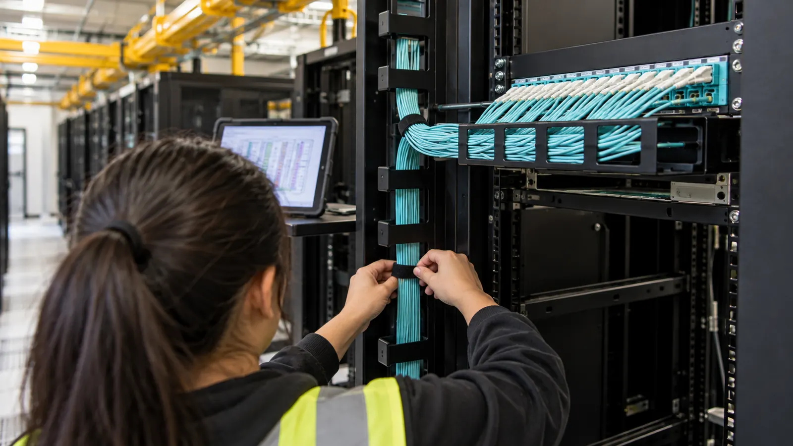
A rack can look orderly while the route feeding it has nowhere left to grow. The next patch cord exposes the problem: a crowded drop, a blocked panel door or a path that crosses an adjacent tenant's space. We address those conditions in the drawings before anyone starts pulling cable.
This guide is for data center operators, colocation providers and developers deciding how the data hall will accommodate change. Our focus is the physical route from the distribution pathway to the equipment port, including the records that let the facility identify and remove a circuit without disturbing its neighbors.
Data center cable management starts in the design
Data center cable management is the design of supported, identifiable cabling routes that remain accessible as connections change. We coordinate 2 scales: shared pathways across the data hall and cable handling at each rack. The design establishes usable capacity and cable protection before the facility's contractor installs the cabling.
The starting point is the operating model. A facility with frequent tenant changes needs accessible patching boundaries; a stable equipment row may place more emphasis on fixed trunk routes. We ask where changes will occur and who may enter that space. That access requirement shapes the layout: a technically reachable panel can still be unusable if the person authorized to change its circuits cannot reach it without entering another controlled area.
Resolve the route before selecting managers
A plan view alone hides vertical conflicts. We develop the route in section where it passes other services or enters a cabinet, because a clear line on the floor plan can become an impossible turn above a rack. By showing the elevation at that crossing, we give the installer enough information to follow the transition without inventing a new path around a support.
That route also needs a defined endpoint. A distribution cable should arrive where the patching arrangement expects it, with space to secure the cable independently of the connector. We review the equipment layout against the pathway exit before fixing the rack elevation. Otherwise, a late panel relocation can consume the space intended for cable management and force cords across working access.
For the wider facility boundary, our colocation inside plant engineering guide covers the handoff between building infrastructure and tenant connections. Here, we follow the pathway within the hall. The distinction keeps the cable-management drawing focused on physical access while the overall structured cabling design establishes where each connection belongs.
Use standards for their separate jobs
ANSI/TIA-942-C, Telecommunications Infrastructure Standard for Data Centers, published in 5/2024, provides the data center infrastructure framework. ANSI/TIA-568.3-E, Optical Fiber Cabling and Components Standard, published in 9/2022, addresses the fiber components and performance requirements within the TIA-568 family. We apply those references to the relevant scope rather than treating a reference on the cover sheet as a completed design.
BICSI practice adds design context through ANSI/BICSI 002-2024, Data Center Design and Implementation Best Practices. Our project basis identifies the applicable standards and accepted facility requirements, including any requirements that exceed the baseline. The owner needs to accept those decisions, including how a different naming or patching convention in an existing facility will connect to the new work before drawings reach the contractor.
Power and telecom separation belongs in that coordination. We show distinct routes and resolve crossings with the electrical designer using the applicable requirements for the wiring systems involved. Optical fiber's immunity to electromagnetic interference does not remove the physical access and safety reasons for coordinating its route with power infrastructure. We also account for cable construction when establishing separation, since a universal distance would conceal the conditions that govern each crossing.
Cooling and airflow enter the pathway review as coordinated constraints, with cable routes kept clear of the facility's intended air distribution paths. The remaining decisions concern access and cable protection. We prefer accessible overhead telecom routes where the building geometry allows them, but a limitation of that approach is the working space required above populated racks when cables need to change.
Compare overhead and underfloor pathways
Overhead and underfloor routing are location choices; ladder rack and tray describe the support arrangement. Fiber raceway serves a more specific protection role and can coexist with either location strategy. We compare them by the work that must happen after occupancy. The table separates those decisions so a support type does not become a substitute for a route plan.
| Pathway arrangement | Useful application | Design check | Change constraint |
|---|---|---|---|
| Overhead ladder rack | Supported distribution cable above rows | Cable support and protected drops | Reach above occupied racks |
| Overhead cable tray | Coordinated routes with defined loading | Fill and support capacity | Access at branches and crossings |
| Underfloor pathway | Facilities with usable raised-floor routes | Tile access and rack entry geometry | Work beneath occupied equipment areas |
| Dedicated fiber raceway | Protected optical patch-cord distribution | Supported exits and bend control | Congestion at outlets and transitions |
Overhead ladder rack
Ladder rack can provide an accessible route for suitable distribution cables, provided its support arrangement matches the cable and the intended loading. We detail how the cable leaves the rack and reaches the cabinet instead of allowing it to hang over an unprotected edge. Supporting the drop through that turn protects the cable where an otherwise neat horizontal bundle reaches its destination.
Open access helps inspection, but the route still needs coordinated support locations. The installer must be able to place or remove cable without using another service as a handhold or resting the bundle on unrelated infrastructure. In our review of the actual work position, we identify whether safe access requires moving equipment so the facility can consider that restriction before accepting the route.
Overhead cable tray
Cable tray design brings the support system and the cable schedule together. The selected tray must suit the cable construction, and its fittings must preserve the route through changes of direction. We check the supports against the planned loading rather than assuming that a wider tray solves every capacity problem. Our schedule keeps structural capacity and usable cable space as separate checks so reviewers can see which requirement governs the selected tray.
A branch can govern the entire route. Where several rows converge, the shared segment may carry substantially more cable than an individual row pathway, even though both appear as the same line weight on the drawing. We carry those accumulations into the schedule, showing where the cable population increases and which support arrangement must accommodate the combined load before the route splits toward individual cabinets. That makes the reason for a larger segment visible when procurement reviews the materials.
Underfloor pathways
An underfloor route earns its place when the facility has accessible raised-floor space and a workable route to each cabinet. Our review includes the approach to the opening and the working space needed to keep the tiles serviceable. A pathway directly below a fixed obstruction can be difficult to maintain even when its initial installation fits within the available void.
Floor plans should identify where the cable crosses beneath equipment or other services. The route needs defined support and protected cabinet entries, with cable ratings selected for the actual environment. Loose cable on the floor creates an uncertain route for future work. For an existing hall, verify the concealed condition before using an old drawing as proof of spare space.
Dedicated fiber raceway
Fiber raceway provides a controlled route for optical cords when its fittings and exits match the planned distribution. Our design checks the route through the outlet and into the manager, where the protective channel ends. At this easily overlooked transition, a congested exit can force cords against its edge even when the straight section has ample room.
To protect exposed patch cords, we keep heavy distribution cables from bearing on them and specify suitable support through changes of direction, including the point where the cord leaves the protected channel. Within our data center fiber engineering scope, this is a coordination problem between the cable schedule and the physical layout. The raceway should serve the planned patching pattern without encouraging shortcuts across unrelated equipment.
Carry the route through the rack
The last part of the route often has the least space. A cabinet entry can satisfy the room layout while leaving cords unable to reach the intended ports cleanly. We therefore review the rack elevation with the pathway plan. Checking both views together lets us trace the cable to its termination and confirm that the proposed route preserves the equipment's service access.
Vertical and horizontal managers
Vertical managers carry cords between elevations and provide an organized approach to the horizontal manager or equipment connection. Their usable space depends on the cord population and how cords enter from either side. We check the populated arrangement, including the space needed to handle a connector, rather than judging capacity from the empty manager's appearance.
Horizontal managers control the approach across the rack face. They need to work with the panel orientation and the equipment's service requirements, especially where sliding assemblies change position during maintenance. We check the route with the cover closed as well, because cords must fit within the finished installation while allowing doors to close freely.
On the drawing, our review also follows the removal path. If a failed unit needs to slide out, the cable arrangement must permit the manufacturer's intended service movement without transferring tension to neighboring ports. The facility should review and accept that service movement as part of the rack layout before the contractor builds around it.
Bend radius and slack
Bend radius comes from the selected cable's requirements under the relevant condition, including the distinction between installation under tension and its installed state. Rather than assigning one radius to every fiber cable, we put the applicable requirement into the detail and check it at each transition, where a nominally generous route can tighten around a fitting or manager.
Check the exit detail: Trace the cable through the drop into the rack with the actual bend requirement in view. Review the smallest turn, even when the straight pathway has ample spare space.
We assign a location for slack where reserve cable can be supported and retrieved without filling the working portion of the pathway or covering a neighboring termination. Selecting patch-cord lengths for the approved route avoids the storage demands of oversized cords and the diagonal shortcuts that undersized cords encourage, which make the next change harder to trace.
Retention should hold the cable without deforming its jacket or forcing an abrupt bend. The design identifies suitable restraint methods and leaves the contractor to install them according to the approved details and component instructions. During review, we look for unnecessary strain at the breakout, which a tightly restrained, uniform-looking bundle can conceal.
Size pathways for usable growth
Spare ports and spare pathway capacity describe different resources. A panel can accept another connection while the shared route to that panel has reached its design limit. We evaluate the installed population and the owner's intended growth case separately. For that growth case, the design should show which future rack positions the reserved space can serve, so a later row extension does not depend on crossing a tenant boundary that the operator cannot release.
Fill, loading and the controlling segment
For the fill calculation, we use the applicable pathway requirements and the selected cable dimensions, with the basis recorded in the schedule. Fiber count alone cannot establish occupied space because cable constructions with the same fiber count can have different outside diameters. We check loading alongside fill because usable reserve ends where either the cable-space limit or the support-system capacity is reached.
The governing point may be a shared branch, a sleeve or a cabinet drop rather than the longest straight run. Our capacity review follows the route through those restrictions, including the space needed to place a new cable without pulling an existing cable out of its supported position. A future row has no usable reserve if its cables cannot pass the transition serving it, regardless of the open space farther upstream.
For redundant services, we review the physical routes independently. A and B labels do not demonstrate separation if the paths share the same vulnerable passage. The meet me room design discussion addresses that issue at the interconnection space; the data hall drawings need to preserve the intended route separation beyond that boundary.
To keep future capacity available, we ask the facility to identify who may allocate reserved space and what triggers a design review when the expected cable population changes. Otherwise, successive small additions can consume the reserve without anyone seeing the cumulative effect. Record the allocation with the route, so its purpose survives staff changes.
Keep labels and records tied to the route
A label becomes useful when it leads to a trustworthy record. ANSI/TIA-606-D, Administration Standard for Telecommunications Infrastructure, published in 10/2021, provides the administration framework for identifying infrastructure and associating it with records. We carry that framework into the facility's naming convention. The identifier must remain intelligible between drawings and the maintenance system, where jacket color alone cannot reliably identify the cable.
Identify both ends and preserve the path
Our cable schedule ties the cable identifier to its endpoints and assigned route. Rack and panel references must agree with the installed labels, and the record should distinguish an available position from an occupied position awaiting removal. Keeping those states separate helps us avoid directing a technician to a port that is still supporting service.
Moves and adds need an agreed update sequence. The person authorizing the change identifies the intended connection, and the completed work returns through the facility's verification process before the operating record is accepted. For the order itself, the data center cross connect guide covers the connection and test boundaries. Our cable-management records connect that order to a physical path that staff can trace during subsequent changes.
For removals, we require the facility's authorization before an abandoned-looking cable is treated as removable, since appearance cannot establish service status. Once the facility confirms removal, the route record can release the occupied capacity. Leaving unidentified cable in place creates an inventory problem that a larger tray will only postpone.
Issue a package the contractor can build
Draftech International is a turnkey telecom and power infrastructure company, covering fielding, planning, construction drawings, permits, agency coordination, construction, as-builts and closeout through one accountable team. Engineering stays entirely in-house; our turnkey construction uses Draftech-managed subcontract crews under our QA/QC and safety program. For this data hall scope, we design the cabling and pathways entirely in-house and issue a construction-ready package through our inside plant design service. The facility's own cabling contractor installs, terminates and tests the system. We define the drawing requirements and the handoff, including how the contractor records a deviation when an installed obstruction prevents the route from following the issued detail. The contractor's field changes must return for review so the accepted records describe the installation.
Responsibility should be visible before procurement. The package needs enough coordinated detail to establish the route and enough specification detail to establish the required cable handling, with unresolved interfaces identified for disposition. Our partner and company information identifies the team behind the engineering. The facility retains control of access and operational acceptance.
Data center cable management decisions before release
Data center operators: Start with the changes your staff must perform around occupied racks. Verify service access before accepting a denser panel arrangement, and make record updates part of the change procedure. Our recommendation is to resolve the congested transition first, because spare capacity elsewhere cannot make that transition maintainable.
Colocation providers: Define the boundary between shared distribution and tenant-controlled cabling before allocating pathway space. Keep capacity reservations tied to the areas they serve. We recommend an approved patching convention that lets authorized staff follow a connection without entering unrelated tenant space or moving another tenant's cords.
Developers: Coordinate the pathway elevations while the building services and rack layout can still be reconciled. Require the future population to appear in the design basis. We recommend resolving supports and cabinet entries before the package is released, so the contractor receives a route that can be built as drawn.
Blocked drops and untraceable cords begin as unanswered design questions. We turn those questions into coordinated pathway details and cable records for the facility's installer; send the proposed hall layout and operating requirements to info@draftech.com or use our project contact page to discuss the design scope.
For a qualifying route associated with the wider connectivity project, Draftech's free engineering offer covers the first 20,000 linear feet at no cost, from feasibility and field survey through permit approval. The owner reviews each request before Draftech commits the package. The offer concerns qualifying route engineering; the data hall scope is defined separately.