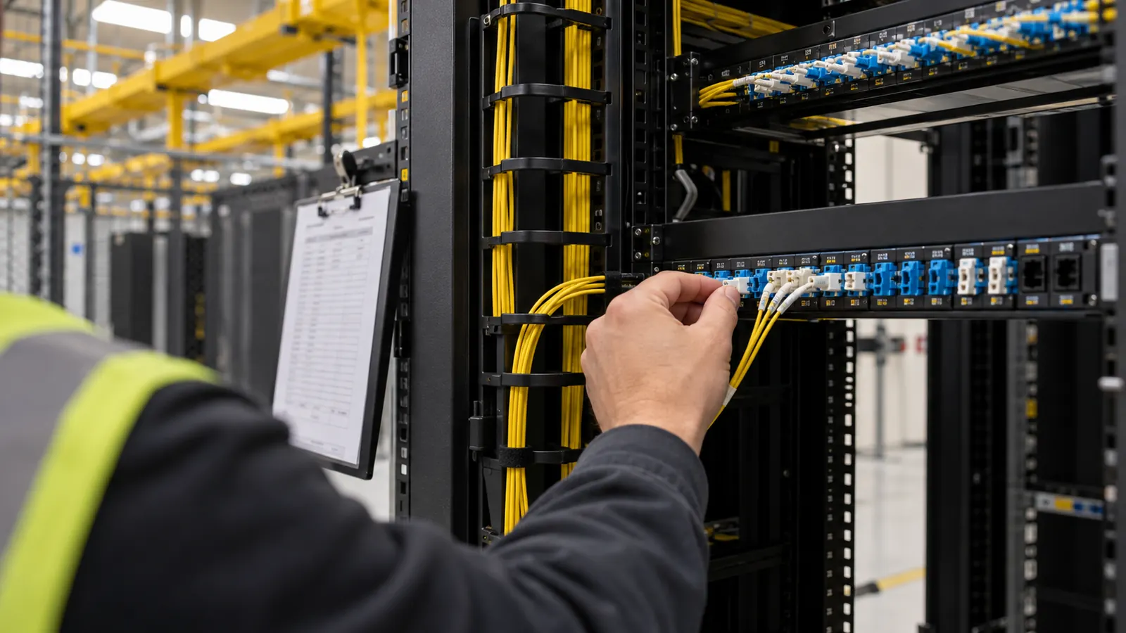
A cross-connect order can look complete while leaving the installer with an unresolved endpoint. The customer names a router port, the carrier names a panel position, and the facility still needs a permitted path between them. We treat that gap as an engineering decision before anyone touches a live panel.
This guide follows a single connection from request through acceptance, then examines the structured cabling that supports repeated orders. Our focus is the physical plant inside a colocation facility. Network configuration remains a separate responsibility, even when the same service ticket tracks the cable installation and the eventual circuit activation.
What a data center cross connect includes
A data center cross connect is a physical cable connection inside a colocation facility that links one customer's equipment to another customer's equipment or a carrier. It commonly uses single-mode or multimode fiber, sometimes copper; a conventional duplex optical connection uses 2 fibers, with the actual media and termination determined by the service interface.
The connection has defined endpoints. Those endpoints may be equipment ports, but a facility can deliver its work at demarcation panels and leave the final equipment jumpers to the customer. We draw that boundary explicitly because a test between facility panels says nothing about a customer patch cord installed afterward. The service order should identify who completes each remaining segment.
Physical connectivity and service activation
Physical completion establishes the cable path and its acceptance evidence. Service activation establishes whether the connected equipment exchanges the intended traffic. A correctly installed fiber pair can still present a dark interface if the remote equipment is disabled, and a link light alone cannot establish that the service configuration meets the customer's requirements.
We separate those acceptance decisions. For a hypothetical order with 2 demarcation panels, our drawing identifies the facility-owned segment between them and shows the equipment jumpers outside that boundary. The customer can then reconcile the installation notice with its own network work without assuming that every segment was tested together or that the carrier has enabled service.
Match the media to both ends
Single-mode and multimode fibers serve different optical interfaces; neither can be selected solely because a matching connector fits the panel. We check the specified fiber category against the transceivers and the full channel length. A connector also has a mating geometry and polish requirement. Physical fit proves very little. An incompatible optical interface remains incompatible after a clean installation.
Copper cross connects need an equally explicit interface definition. Balanced twisted-pair service requires the specified category and channel performance, while other copper presentations may use different cable and termination arrangements. We ask the service owner to settle the interface before reserving materials. Substituting an available copper cable for an unspecified presentation transfers a design decision to an installer who may lack the equipment requirements.
Order the data center cross connect with usable endpoints
The receiving party's authorization and the facility's work order perform different jobs. A letter of authorization, or LOA, permits the requested connection to the receiving party's designated termination. The connecting facility assignment, or CFA, identifies that termination within the facility. They may arrive together as an LOA/CFA, but an authorization still needs enough location detail to direct the work.
We reconcile the names first. The building identifier and the panel designation must agree with the facility's records, even if the carrier's portal uses a different alias for the same location. The requester's endpoint needs equal precision. An order that identifies only a company and a rack leaves the actual landing position unresolved.
Resolve the assignment before dispatch
A usable CFA points to a specific termination, with the facility's hierarchy carried through to the port or fiber position. That hierarchy can include a room and cabinet, with a panel position beneath them. We retain the receiving party's original assignment and map any facility aliases explicitly so the installer can recognize the physical label without rewriting the authorization.
A changed assignment needs confirmation. If the assigned port appears occupied, the installer should stop that portion of the work and return the discrepancy to the facility's order owner. Moving to the next empty-looking position can connect the wrong service. Our release check also confirms that the order has not been superseded and that the requesting account has permission for the proposed work.
The work package needs a test boundary before installation begins. We specify where the facility's responsibility ends and who supplies the final equipment patching, then identify the approval needed to work near an active circuit. For 2 supposedly diverse orders, we request separate route identities at this stage; assigning different order numbers alone creates no physical separation.
Compare the handoffs before releasing the work
Each handoff below answers a different acceptance question. We use the distinction to prevent an installation notice from closing a request whose test results or operating records are still incomplete. A facility may combine these steps within its own workflow, but the evidence should remain traceable to the same connection identifier and the authorized endpoints.
| Handoff | Required evidence | Stop condition |
|---|---|---|
| Authorization | LOA and resolved CFA | Permission or assigned termination is unclear |
| Provisioning | Reserved route and patch schedule | Field position conflicts with the release |
| Testing | Results tied to the agreed boundary | Measured performance fails the specified limit |
| Operational release | Labels and accepted connection record | Installed path cannot be reconciled with records |
Provision the patch path without losing its identity
The assigned route determines which fixed fibers and patch positions become part of the connection. A meet-me room provides the shared interconnection location where the patch path can pass through carrier and facility cross-connect panels. We keep the work order tied to the actual panel sequence, including intermediate transitions that are easy to omit from a simplified customer diagram.
Build a continuous port-to-port record
A typical arrangement can run from a customer demarcation panel over fixed backbone fiber to a distribution panel, then through a jumper to the carrier's assigned termination. That is an example topology, not a requirement for every building. The facility's approved design controls the route. We record each segment so the installed chain can be followed without opening unrelated circuits.
Port numbering needs careful attention. A duplex adapter position can represent 2 fibers, while a panel's marketing capacity may count individual fiber terminations instead of usable duplex connections. We express both quantities in the schedule. For multifiber connections, the record must preserve the fiber-position map through every cassette or adapter rather than reducing the assembly to a single cable label.
The wider allocation of facility and tenant responsibilities is covered in our colocation inside-plant handoff guide. Here, our immediate concern is that the reserved route matches the release package before a technician starts patching. A local substitution needs an approved record change because it can affect the test boundary and consume capacity reserved for another order.
Control work around existing services
Installation instructions should protect neighboring connections. We identify the authorized panel positions and require cable management that leaves existing ports accessible, with bend radius and pulling limits taken from the selected cable's installation requirements. Excess slack belongs in the intended management space. Hanging a coil across an adjacent panel can make the next authorized change disturb an unrelated circuit.
Access control also applies to test activity. The work owner must confirm that a fiber is released for testing before anyone disconnects equipment or attaches a test source. We keep the rollback path clear where work touches an active service, and the facility decides the permitted maintenance conditions. A generic cross-connect request does not authorize an interruption.
Keep the original assignment attached. When a field label differs from the CFA, resolve the discrepancy against the facility record before connecting. A photograph can document the mismatch, but it cannot authorize a replacement port.
Test, label and accept the installed connection
Acceptance starts with the defined endpoints and the specified test method. Our package identifies the link under test so the results can be compared with the same boundary used in the design. A passing result for one fixed cable segment does not establish the performance of a complete channel that includes additional patch cords and mating interfaces.
Inspect and measure the optical path
Connector inspection precedes mating. We specify inspection and appropriate cleaning with reinspection, using an approved inspection instrument and the facility's optical safety procedure. The test plan should preserve the condition of the reference cords because contamination there can invalidate a result before the installed cable contributes any loss. Repeatedly reconnecting a dirty test lead can spread contamination between ports.
The Fiber Optic Association's Fiber U Quickstart Guide: Fiber Optic Testing identifies source-and-power-meter testing as the means of measuring installed optical loss. We require the chosen wavelengths and reference method to be recorded with the measured result. An optical loss test set, or OLTS, supplies insertion-loss evidence; continuity and polarity checks establish that the assigned fibers reach the intended positions.
An OTDR can locate events and support fault investigation when the test specification calls for it. Its usefulness on a short cross-connect depends on instrument resolution and the test setup. Closely spaced events can overlap. We do not use a visually clean trace as a substitute for the specified end-to-end loss measurement, particularly when the acceptance question concerns a short patched link.
The allowed loss comes from the documented link design and applicable interface requirements. We account for the actual connection interfaces rather than approving every cross-connect against a single assumed limit. If a measured value fails, the repair record should identify what changed and retain the final retest. A result becomes useful only when someone can reproduce its boundary and method.
Make the labels agree with the results
A connection identifier belongs at both ends and in the operational record. We pair it with endpoint references that remain readable after the cable is routed into its manager. Color can help recognition, but the label carries the identity. Copper installations need their own specified certification evidence; an optical loss result cannot establish balanced twisted-pair channel performance.
Our acceptance record links the installed path to its test files and the completion approval. For a duplex service, both fibers need identifiable results, including the polarity mapping that connects transmit to receive as required by the equipment. Both fibers must pass. The record should show which result belongs to which physical position.
Verify labels at the final routing position. Check that the identifier remains visible after the cord enters its cable manager. A label hidden behind the panel makes future verification harder precisely where a technician needs to avoid disturbing adjacent services.
Disconnects need the same discipline. We retain the closed service's history while changing the released resources to the correct operational state, and we remove abandoned jumpers only through the facility's approved process. Otherwise, an empty port can remain reserved in the database while an occupied position appears available. Neither discrepancy is solved by adding more rack space.
Design pathways and panel capacity for repeat orders
A scalable design connects physical capacity to assignable capacity. Spare fibers in a backbone cannot serve a new order if their terminations are inaccessible or the connecting pathway has no room for another managed jumper. We assess the whole route. Our inside-plant structured cabling design addresses those dependencies before incremental orders consume the usable space.
Use standards as a design basis
ANSI/TIA-942-C, Telecommunications Infrastructure Standard for Data Centers, published May 2024, addresses data-center infrastructure and topology. ANSI/TIA-568.3-E, Optical Fiber Cabling and Components Standard, announced by TIA on September 29, 2022, addresses premises optical-fiber cabling, components, connectivity and test requirements within the TIA-568 series. We identify the project-adopted editions in the design basis and reconcile them with the facility's own requirements.
These references operate at different levels. TIA-942 informs the broader infrastructure arrangement, while TIA-568.3 informs the optical cabling, component and testing specifications. Neither replaces a carrier's port assignment or the facility's work authorization. Our drawings translate the adopted requirements into buildable routes and termination schedules, and unresolved requirements go back to the responsible design authority before installation release.
Count usable fibers and patching space
Consider a planning example with a 48-fiber backbone allocated entirely to conventional duplex services. Dividing by 2 gives 24 possible fiber pairs before reservations or unavailable strands are considered. That arithmetic is a ceiling, not an order commitment. If 4 pairs are held for a documented purpose, only 20 pairs remain available under that allocation, assuming every required termination and pathway is usable.
Panel capacity must use the same units. We distinguish individual fiber positions from duplex adapter positions and show which backbone fibers land at each one. The schedule also separates reserved capacity from installed working services. A total that combines both states can mislead an operator into assigning a resource already promised to a pending customer order.
Pathway design needs room for maintenance. At a congested panel, another technically available port can be impractical to reach without moving live cords. We check the routing approach and the cable-manager access against the planned population, including how staff will replace a damaged cord. Our data-center fiber design discussion places that patching detail within the wider plant architecture.
Preserve separation and keep records current
Two connections can share a failure point even when their labels say A and B. We trace any requested diversity through the physical route and identify common infrastructure explicitly. Different panel positions do not establish route diversity. If both paths enter the same constrained pathway, the design needs to disclose that shared exposure so the owner can evaluate it.
The limitation of our preferred fixed-backbone approach is that spare strands help only where the installed backbone already reaches; a new destination may still require another pathway or cable. We therefore map expected demand by destination instead of specifying one blanket spare-fiber percentage. This makes expansion decisions visible before the facility accepts an order it cannot serve with existing plant.
Records must change with the work. We recommend reservation and release controls that prevent simultaneous orders from claiming the same fiber pair, with completed field changes reconciled before capacity returns to the available pool. Our data-center fiber infrastructure services connect those operating requirements to the physical design, so capacity reports describe resources staff can actually use.
Set the next decision by your operating role
Data center operators: require an accepted connection record before closing the installation task. Keep physical completion separate from service activation, and make the test boundary visible to the customer. For a request involving 2 diverse connections, require route evidence for each path. That gives operations a defined basis for investigating trouble instead of relying on an order's completion timestamp.
Colocation providers: manage reservations at the panel and fiber level. Reconcile released orders with the capacity inventory before accepting further assignments on those positions. We recommend a destination-based expansion review whenever orders repeatedly need routing exceptions, because a building-wide spare count can conceal a shortage between the particular locations customers need to connect.
Carriers: issue an unambiguous CFA and confirm how the facility will identify your termination. Keep assignment changes tied to the original order, and state who owns the equipment jumper beyond the demarcation. Those decisions let the customer distinguish an incomplete physical path from a service awaiting network activation without asking an installer to infer your intended interface.
Draftech International delivers turnkey telecom and power infrastructure with engineering performed 100% in-house and full turnkey construction delivered by Draftech-managed subcontract crews under Draftech's QA/QC. Our partner responsibilities identify the people accountable for delivery. For an inside-plant scope, we connect the endpoint decisions to construction drawings and carry the installed changes into as-builts and closeout; discuss your facility's handoff requirements at info@draftech.com.
Bring us the endpoints and the capacity problem. We can define the design scope around the connection your facility needs to deliver and the records its operators need afterward.
If the capacity review also identifies a qualifying route outside the building, our free engineering offer provides the first 20,000 linear feet at no cost, from feasibility and field survey through permit approval. The owner reviews each request before Draftech commits the package, so the route request starts with that review and a clearly defined engineering scope.