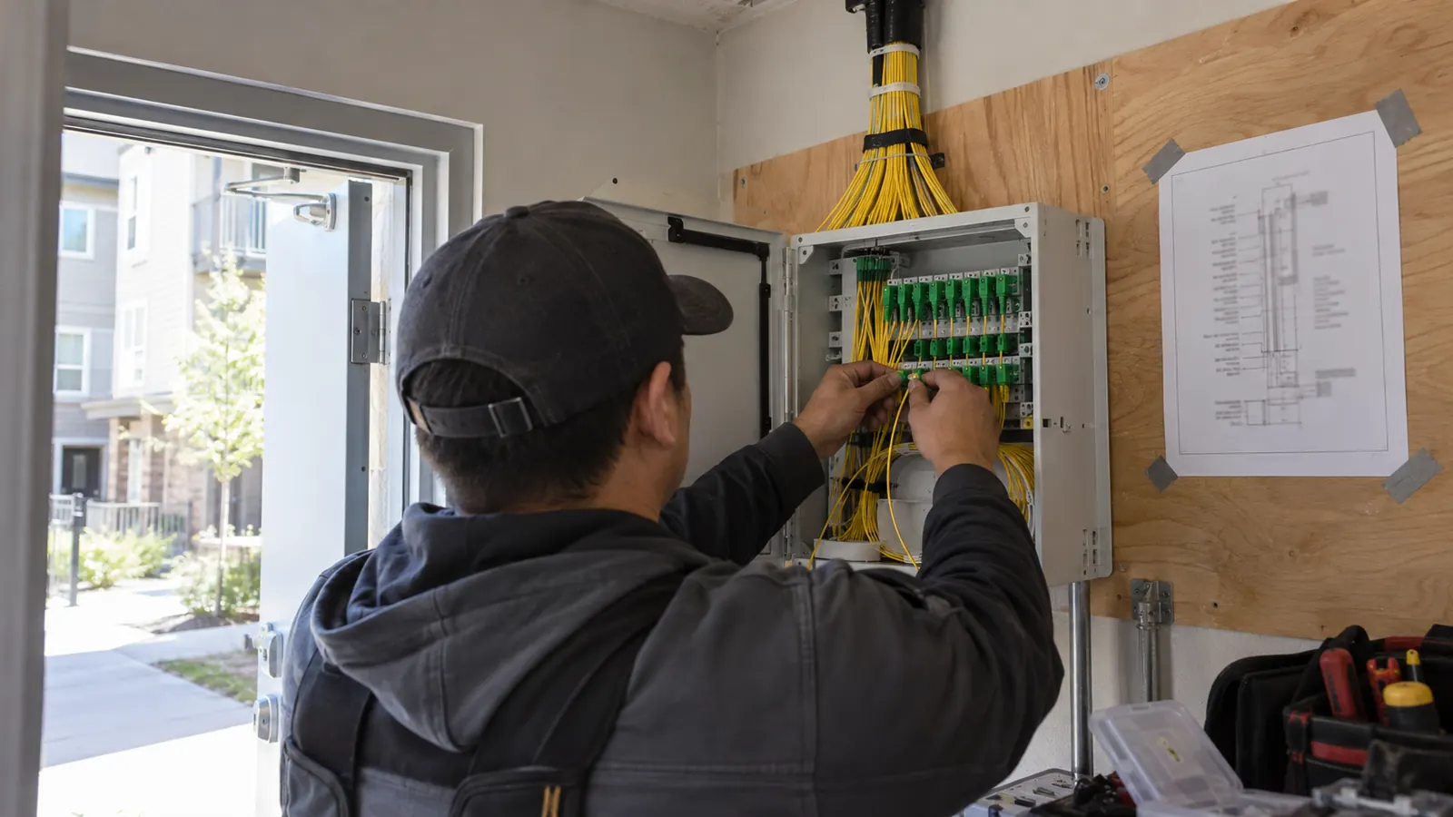
- MDU fiber installation starts with an approved building route
- Bring fiber through the entrance and the building pathways
- Choose the MDU distribution arrangement around access
- Coordinate MDU fiber installation from mobilization through testing
- Next steps for owners, developers, and ISP deployment managers
An apartment building can have fiber at the property line and still lack a workable route to its residents. The difficult part may be a locked riser closet or a corridor finish the owner will not allow anyone to disturb. We start with those building conditions because they determine what a crew can install without leaving an unfinished path outside an apartment door.
This guide follows the work from the entrance through the unit connection. We explain where distribution choices change the construction scope and how owner coordination carries into acceptance. The focus is fiber to each dwelling, with the service provider's optical network terminal, or ONT, located at or inside the unit.
MDU fiber installation starts with an approved building route
MDU fiber installation brings an outside fiber connection through a shared building network to individual dwellings. A passive optical network can use 1 centralized splitter location or distribute splitting closer to the apartments. The route must connect the entrance to each unit through usable pathways, with property access settled before construction.
The first design decision is the service boundary. We ask the provider to identify where its outside plant ends and who owns the cabling beyond that point. A property-owned backbone and a provider-owned backbone can occupy similar physical space but require different maintenance arrangements. Set the boundary first. We put it on the drawing because a fault that crosses from the provider's outside plant into a property-owned backbone needs a clear handoff between the people authorized to investigate each side.
Walk the property with someone who can authorize access
A useful walk includes a property representative who can open the spaces that the proposed route needs. We compare the floor plans with visible conditions and mark any section that remains unverified. A shaft drawn on an architectural sheet may have been altered during renovation; a route through a resident's storage area may be physically possible but unavailable for routine maintenance.
Owner coordination should produce a usable work agreement. Who authorizes apartment entry? We establish that responsibility and how residents receive notice. The agreement also needs a process for missed appointments, since a resident who cannot provide access on the scheduled day leaves a different problem from a blocked shared conduit. Keep those exceptions separate in the installation log so the next visit has a clear purpose.
Set the unit scope before pricing the installation
We distinguish a building ready for future drops from a building with completed apartment connections. The owner and provider should agree on the required endpoint before proposals are compared. A terminal outside an apartment, a fiber outlet inside it, and an activated ONT represent different completion states. The contractor's scope should name the state being purchased rather than relying on the word connected.
Apartment finishes deserve an early decision. We ask the owner to approve the visible pathway treatment and the method of making good disturbed surfaces. A small sample installation can settle appearance before the same detail is repeated through an occupied corridor. The sample needs to include the awkward doorway or corner that will recur, because a straight section alone says little about the finished result.
Bring fiber through the entrance and the building pathways
The entrance ties the outside route to the internal network. We place it where the incoming cable can reach a secure termination location and where maintenance access can be sustained after construction. An available wall near the property boundary may still be a poor choice if servicing the enclosure would block a regularly used doorway. Space is part of the design. We establish the approach before selecting an enclosure, including how a technician will reach the termination when the building is occupied and the doors that surround it are in normal use.
Building entrance and demarcation
At the building envelope, the construction detail must address the penetration and its restoration. We coordinate the proposed opening with the property's building professionals and the applicable approval process. Cable suitability changes with the environment, so the design must identify where an outside cable transitions to an indoor-rated assembly when required. A conduit shown entering a wall does not resolve those details by itself.
Equipment needs working space. We check cabinet access with doors open and consider how a technician will handle spare cable without disturbing active connections. If powered equipment belongs in the room, its power and environmental needs enter the scope separately. Passive splitters need no local electrical supply, while an ONT still needs power at its installed location.
Riser pathways and horizontal distribution
A riser carries the building backbone between levels; horizontal pathways carry the route across a floor toward dwellings. Corning's online Multidwelling Units Fiber Installation Solutions overview describes floor terminals as transition points between these parts of the network. It also notes that a terminal may serve a floor or adjacent floors, depending on the building arrangement.
We trace the proposed riser continuously. Inspecting the accessible top and bottom of a shaft cannot establish what happens between them. Where access prevents verification, the design should show the uncertainty and the construction plan should reserve a way to resolve it before cable is ordered. Our riser cable design guide explains the vertical backbone handoff in more detail.
The table identifies the decisions that follow the route survey. Each choice changes a different part of the installation; the table separates optical layout from cable termination method so an owner can compare proposals on the same basis.
| Installation choice | Where work concentrates | What must be verified | Main tradeoff |
|---|---|---|---|
| Centralized splitting | Common distribution room | Outgoing fiber capacity in the riser | Common maintenance access versus more fiber on shared routes |
| Distributed splitting | Floor or area cabinets | Accessible splitter locations and optical budget | Shorter local drops versus more cabinet access points |
| Pre-connectorized assemblies | Factory termination and site connections | Measured lengths and connector passage | Less site termination versus fixed assembly lengths |
| Field-spliced assemblies | Splice enclosures on the approved route | Splicing access and qualified personnel | Length flexibility versus site splicing work |
Choose the MDU distribution arrangement around access
Splitter placement changes where technicians make subscriber connections and how much fiber must pass through constrained spaces. We evaluate that choice against the provider's network requirements before finalizing the building design. A passive optical network, or PON, shares an optical feed through splitters. Check the complete path. The provider's approved optical loss budget must account for the selected splitting arrangement and the connections between the outside feed and the ONT, with the required operating margin remaining after those losses.
Centralized splitting
Centralized splitting concentrates the building's splitters at a common location, such as a main telecommunications room. Fibers run onward to the apartments, either directly or through intermediate connection points. The Fiber Optic Association's online reference, FTTH in MDUs (Multiple Dwelling Units), describes entrance-facility splitting and contrasts it with cascaded splitting serving floors or building areas.
We favor evaluating a centralized layout when the main room is accessible and the riser has enough usable capacity for the outgoing fibers. Subscriber changes can be handled at a common distribution point. The tradeoff is the cable volume between that point and the units. A compact splitter cabinet cannot compensate for a riser that lacks room for the routes leaving it.
Our own preference for concentrating maintenance can become a design mistake if we treat the main room as the only constraint. We must prove the onward path. In a retrofit, the cost of creating that path may outweigh the convenience of centralized access. Record that tradeoff before procurement, while the layout can still change without stranding purchased material.
Distributed and cascaded splitting
Distributed splitting places splitters nearer the groups of units they serve. A cascaded arrangement splits the signal in successive stages. The FOA reference illustrates a 1:4 splitter feeding 1:8 splitters, producing 32 downstream outputs; this is an architecture example, not a default design for every building. The provider must approve the resulting loss and capacity assumptions.
Floor cabinets introduce recurring access needs. Who holds the keys? We establish that responsibility and whether a technician can reach the cabinet without entering a dwelling. A shorter apartment drop can be useful, but a cabinet located behind tenant-controlled storage creates a maintenance dependency. Put the access requirement into the owner's review while there is still a choice of cabinet locations.
Future service-provider arrangements also matter. Shared pathways and individual fiber ownership need to be distinguished from the PON topology. We identify where fibers could be reassigned and what physical access that would require. If the owner wants multiple providers, the design conversation must include the neutral connection points; changing the splitter arrangement alone does not establish that operating model.
Pre-connectorized assemblies
Pre-connectorized cable arrives with factory-installed connectors. Corning describes pre-connectorized riser solutions for MDU applications in its online overview. These assemblies can reduce termination work at the installation location, but they still need a route that accommodates the protected connector end. They are a cable deployment choice that can support different splitter layouts.
We check the route first. Then we specify lengths against the intended slack locations. Too little length can make an otherwise suitable assembly unusable, while excess cable needs protected storage that respects the manufacturer's bend limits. Confirm connector compatibility with the selected hardware before ordering. Factory termination still leaves inspection and cleaning work at each connection, followed by the agreed acceptance tests.
Field-spliced assemblies
Field-spliced cable gives the installer flexibility to fit lengths to the verified route and terminate fibers at designated enclosures. It also requires a suitable working location and qualified splicing personnel. We identify the splice access points in the construction package so a subcontract crew can plan the work without improvising a splicing position in an occupied corridor.
The choice between factory connectors and field splicing should include future repair access. A replaceable connectorized assembly is attractive where its route remains accessible; a spliced segment may fit better where pulling a replacement connector through the pathway would be difficult. Our MDU fiber engineering service develops the building layout and connection details that support this decision.
Coordinate MDU fiber installation from mobilization through testing
Construction readiness depends on the property being ready to receive the work. We align the approved route with resident access before releasing the affected areas for installation. A crew assigned to a floor with unavailable apartments needs a defined alternative task or a revised visit. Access controls the sequence. When a shared route can be finished before individual apartment appointments, we separate those activities in the schedule so the installation team can continue productive work while the property representative resolves missed access.
Release work in areas that can be completed
Draftech's engineering is 100% in-house. We deliver full turnkey construction through Draftech-managed crews, using subcontract crews under our QA/QC and safety program. The construction manager coordinates their work with the property representative and the engineering team. For owners who need responsibility for field changes and acceptance held together, our fiber construction management support covers that delivery interface.
We release work by an area whose access and restoration requirements are settled. Shared infrastructure can be installed ahead of apartment appointments when the design allows it, but unfinished ends must be protected and identified. The daily record should distinguish installed pathway from tested fiber. Neither tells the owner which apartments are ready for activation unless unit status is tracked too.
Approve the visible route before repeating it. Have the property representative inspect the first completed corridor detail against the agreed sample. Resolve a finish objection there, while the remaining floors can still use the corrected detail.
An unexpected obstruction should go back through engineering before the crew changes the route. We ask for enough field information to compare the proposed alternative with the original design, including its effect on access and restoration. Our fiber construction RFI workflow separates the technical answer from authorization to change the work. That separation helps prevent an informal field suggestion from becoming an unpriced scope change.
Protect the installed fiber and the building
Cable handling follows the selected product's limits. The FOA's Fiber Optic Installation reference distinguishes premises installations from outside plant and emphasizes the installation requirements of each environment. We carry the applicable manufacturer instructions into the work package rather than assuming a small cable tolerates any corner or pulling method. Cable support must suit the route, particularly where vertical weight accumulates.
Penetrations through rated assemblies need the specified firestop treatment and the required inspection. We coordinate those details with the responsible building professionals before the opening is made. Photograph concealed work while it is accessible, and identify the location in the record. The photograph should let the owner connect the completed detail to the drawing without relying on someone's recollection.
Test against the approved acceptance plan
Testing starts with a defined scope. We agree on the optical paths to be measured and the results the provider will accept before installation begins. Connector inspection and cleaning support that work. Where loss testing or optical time-domain reflectometer traces are required, the test method must fit the topology; splitter-based paths need different interpretation from an uninterrupted fiber segment.
Every passing measurement needs an identified connection. We connect each result to the installed fiber identification and resolve discrepancies before handover. A test file named only for a floor is difficult to use when several apartment routes occupy that floor. Preserve the underlying results so the operations team can compare later measurements with the accepted installation.
Next steps for owners, developers, and ISP deployment managers
For owners of occupied buildings: approve the pathway appearance and apartment-access process before accepting a fixed installation sequence. Require the completion report to show inaccessible units separately from construction defects. This gives the property team a practical appointment list and lets the contractor finish accessible work without disguising the remaining resident coordination.
For developers with open construction: settle telecommunications space and pathways while other building systems are still being coordinated. Reserve the designed access points through the finishing work. We recommend reviewing the fiber route before ceilings close because an enclosure that remains visible can still become unusable when later work blocks the approach to it.
ISP deployment managers: approve the optical architecture before ordering the building assemblies, then define acceptance by the service endpoint you are buying. Require an explanation of any unit left short of that endpoint. A building with installed backbone fiber can be ready for subscriber orders without every dwelling being activated, provided the remaining installation obligation is explicit.
The handover should leave the maintenance team able to find an apartment's fiber and understand who may work on it. We reconcile the final route with the connection records and record unresolved access restrictions. Our construction progress reporting guide explains how to distinguish installed work from accepted work as the building approaches handover. Assign the remaining work. Before the construction team demobilizes, the owner needs to know who will return for an inaccessible apartment and how the resulting connection record will be added to the package already handed over.
Discuss your building's fiber installation with Draftech. Bring the available floor plans and the property's access restrictions so the discussion starts with the route the work must use.
Unverified shafts and missed unit access become manageable when building engineering and construction delivery use the same approved scope. We carry that scope through the crew work and the final connection records. Send your building requirements to info@draftech.com. Active in 24 states. Available across all 50 U.S. states.
For a qualifying route feeding the property, Draftech engineers the first 20,000 linear feet at no cost, from feasibility and field survey through permit approval. The owner reviews each request before Draftech commits the package. Submit the route through our free engineering request so its eligibility can be reviewed against the proposed work.