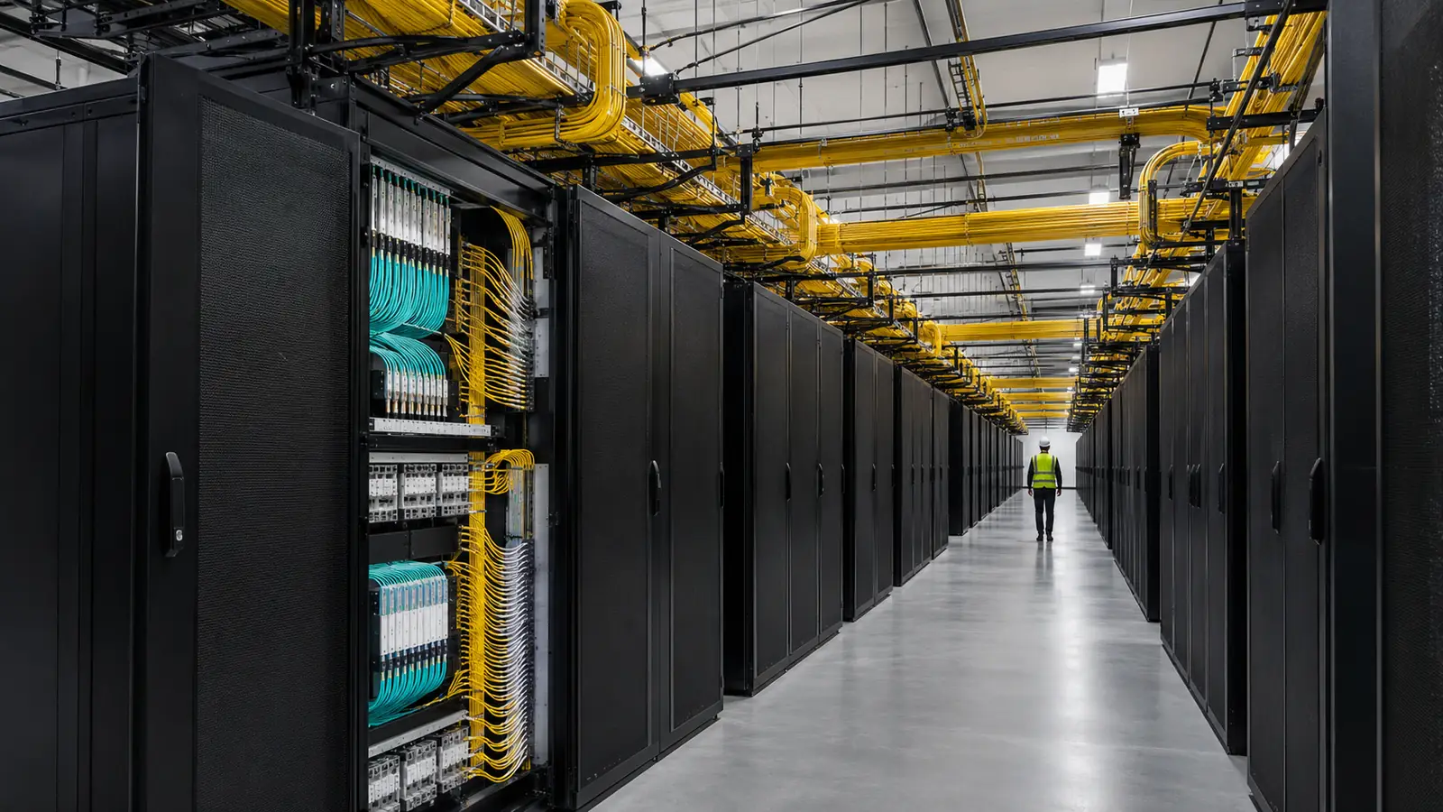
Hyperscale fiber is often reduced to cable count. That misses the harder work: proving physical routes, separating common risks, coordinating outside and inside pathways, preserving endpoint and polarity decisions, tying tests to exact links, and maintaining records that stay useful through continuous change.
This explainer uses Draftech's six-domain review method as company guidance. Project requirements, owner architecture, carrier agreements, security controls, applicable standards, permits and acceptance criteria remain controlling.
What Is Hyperscale Data Center Fiber? 6 Connected Infrastructure Domains
What is hyperscale data center fiber? It is the coordinated outside-plant and inside-plant fiber system serving a large data center campus across 6 connected infrastructure domains: routes, entrances, trunks, pathways, testing and records. The six-domain count is Draftech guidance, not an industry measurement or a universal architecture requirement.
The defining feature is not one special cable. It is system coordination at campus scale, where carrier paths, property entrances, inter-building routes, distribution spaces, patching, optical links, work orders and inventory must agree. A higher fiber count cannot correct a shared route risk, congested pathway, unclear demarcation or record that cannot trace a circuit.
The Telecommunications Industry Association provides the named standards context. Its TIA-942-C data center infrastructure white paper describes minimum design guidance across power, mechanical systems, architecture, security and telecommunications cabling. We use that source for domain context, while the controlling project documents determine the actual design and acceptance.
What Is Hyperscale Data Center Fiber as an Engineering Boundary?
We begin by defining limits: carrier or long-haul interface, campus boundary, outside-plant structures, building entrance, inside-plant pathways, distribution points, panels, ports and owner systems of record. Those limits are Draftech planning guidance rather than universal demarcations. The project owner and involved providers establish actual responsibility, access, security and acceptance boundaries.
A controlled basis file then names source records, route evidence, owner decisions, approved architecture, test requirements, record systems and open exceptions. We use stable identifiers across route segments, structures, cables, closures, panels, ports, tests and final records. Without that naming discipline, separate teams can produce technically correct files that cannot be reconciled into one operational system.
Draftech performs data center OSP engineering in-house. Our data center fiber services connect survey, route design, permit packages, submissions, closeout and campus documentation. Where construction is included, full turnkey delivery uses Draftech-managed subcontract crews under our QA/QC and safety oversight, not management-only and not a claim that all physical work is self-performed today.
Route exceptions should remain visible after a preferred path is selected. We preserve the affected segment, source condition, alternatives, technical decision, required authority and approved response. That history helps future expansion teams understand why a path changes without treating the old decision as permanent. The companion OSP engineering partner guide expands that coordination. New work still requires review against current facilities, access, agreements and owner requirements. This controlled basis carries forward into every later route, splice, permit and closeout decision.
| Infrastructure domain | Primary engineering question | Operational record |
|---|---|---|
| Campus routes | Where does the physical path run? | GIS, structures, access and route status |
| Diverse entrances | Which failure dependencies are actually separated? | Path evidence and approved exceptions |
| Fiber trunks | How do counts and endpoints support the architecture? | Cable, fiber and connectivity inventory |
| Pathways | Can cables be installed, protected and maintained? | Duct, tray, room and occupancy relationships |
| Testing | Do results prove the specified link? | Test files tied to endpoint identifiers |
| Records | Can operations trace current installed state? | Drawings, GIS, work orders and issue history |
Physical diversity must be physical. Diagram lines prove nothing. Trace the route.
Design Campus Routes and Diverse Entrances as Physical Systems
Campus route design starts beyond the final building wall. We map the approved corridor, structures, pathways, crossings, entrances, building transitions, and access conditions under stable route identifiers. The drawing should explain physical continuity and responsibility without implying that a carrier's logical service name proves the actual field path or absence of shared dependencies.
Diversity is a physical claim that needs evidence. Two fibers, cables, or providers can still share a structure, pathway, entrance, room or other common risk. We define the failure conditions the owner requires the design to address, then trace each proposed path against the available route evidence. We do not invent a universal separation value or resilience tier.
Route records should distinguish observed facts, provider records, engineering assumptions, approved decisions and open verification. A colorful route map is not proof when the source for a critical segment is unclear. Our QA review follows the path across maps, drawings, permits, field evidence, and owner decisions so an apparent split cannot hide a shared approach or transition.
The last-mile fiber design guide explains the outside route and permit discipline that can feed a campus design. At the campus boundary, we preserve provider, owner, demarcation, splice, and access decisions without assuming that one party's record automatically controls another party's facilities. Interfaces must be explicit.
Entrances and inter-building routes also interact with physical security, fire protection, architecture, and facility operations under the project's controlling requirements. We coordinate those interfaces without presenting this article as a full facility standard. The design team must use the applicable criteria, approved pathways, and named authorities for the actual building and campus.
For a hyperscale data center campus, Draftech completed 28 route-miles of work and delivered the survey plus OSP design and permit packages, with submissions completed in 17 days; closeout documentation was completed. This is the only approved project descriptor and data. It shows how one controlled workstream can connect route evidence, design, permitting, submissions, and records without identifying the client or location.
That proof point does not become a universal schedule or productivity claim. We do not infer that another campus, route, authority or scope will follow the same duration. The useful lesson is the integration model: align source data, engineering, permit decisions, submission evidence, and closeout under one issue structure so handoffs do not create avoidable gaps.
Capacity needs a source. Labels need owners. Tests need endpoints.
Coordinate Fiber Counts, Pathways, Patching, Polarity, and Testing
Fiber count belongs to an approved architecture and capacity model, not a generic hyperscale number. We connect cable type and count to endpoints, distribution hierarchy, growth assumptions, pathway availability, splicing, panels, ports, patching and operations. The owner decides required reserves and planning horizons. This guide does not invent counts, occupancy targets or utilization statistics.
Pathways have physical constraints that must agree with the cable plan. Duct, innerduct, tray, raceway, sleeves, risers, rooms, and maintenance access are evaluated under the applicable project criteria. We preserve occupancy and route relationships where required, but we do not state a universal fill, bend, separation, or working-space value without a verified controlling source and context.
Distribution and patching design should make the approved connectivity serviceable. Cable, closure, frame, panel, cassette, port, patch, and endpoint identifiers need a controlled hierarchy that operations can trace. High density magnifies naming mistakes. A valid optical design can still fail during turn-up if two teams use different endpoint names or if physical patches outrun inventory updates.
Polarity decisions belong in the accepted design and work instructions for the selected components and architecture. We do not publish a generic method as the universal answer. The responsible engineers and owner establish the required approach, labels, inspections and acceptance. Changes must move through controlled work orders so the physical link, records and tests stay aligned.
Testing proves the specified link when the result is tied to the correct endpoints, fiber identity, method, criteria and disposition. We do not invent loss limits, wavelengths, test directions or retest rules. The approved test plan controls those details. A passing summary without traceable files can be operationally weaker than a visible exception with clear ownership.
Draftech campus guidance: trace pathway, cable, fiber, endpoint, patch, and test as one relationship before accepting a capacity or performance statement. The six-part trace is company guidance, not an industry measurement.
The fiber network design software comparison explains why system selection follows data ownership. At data center scale, the same principle reaches inside the campus: no tool can reconcile undefined identifiers, missing demarcations, unapproved changes, or tests that were never tied to the installed path. Process and data model come first.
Capacity records should distinguish installed, assigned, reserved, available, and unknown status using the owner's approved definitions. Those labels are not interchangeable, and this article does not prescribe universal thresholds. We require the source and approval path for a capacity change so planning cannot count the same pathway, fiber, panel position, or port in conflicting systems or treat an unverified blank as available infrastructure.
Keep the demarcation explicit. Responsibility follows it. So does access.
Keep Outside Plant and Inside Plant Boundaries Explicit
OSP and ISP teams often use different drawings, systems, terminology, access controls and acceptance processes. We define the transition structure, entrance facility, ownership, cable and pathway continuity, splice or connector interface, grounding or bonding responsibilities where applicable, and record handoff under the project's approved requirements. The boundary should be traceable, not merely understood by current staff.
A responsibility matrix is useful when it names decisions rather than departments. We identify who approves the outside route, entrance, inside pathway, cable selection, connectivity, testing, record update and field change. That matrix is Draftech planning guidance, not a universal staffing model. Owners can allocate roles differently as long as every interface has authority and evidence.
Field changes at the boundary need cross-discipline review. A changed entrance, pathway, closure, cable, or endpoint can affect route permits, pull planning, inside distribution, testing, security and final records. We capture the observation, technical effect, approvals, accepted response, implementation evidence, and data updates in one decision record while preserving each discipline's acceptance.
Construction delivery follows the same boundary discipline. Draftech's engineering is in-house. Full turnkey construction is delivered through Draftech-managed subcontract crews under Draftech QA/QC and safety oversight. This creates one point of accountability for accepted scope without claiming every physical task is self-performed and without reducing the service to oversight alone.
For owners with established OSP, facility, and network integration teams, separate design contracts can work when the owner controls the interfaces. For a campus with unclear demarcations or fragmented records, our recommendation is direct: define the boundary and data ownership before final cable and pathway decisions. Waiting until commissioning turns design ambiguity into operational reconciliation.
Security and access fields should be handled through the owner's approved information controls. The operating record needs enough authority and location context for qualified users to perform their work without publishing sensitive details in general documents. We identify record ownership and access status, but we do not invent a universal security classification. The owner's policies and project requirements determine storage, distribution and review.
Operations inherits the record. Make it usable. Test the chain.
A candid limitation of our connected-record approach is that it creates more identifier governance at the start, before separate OSP teams or campus operators feel the pain of conflicting files. That work is real. Our in-house engineering model controls the relationships, while the owner still defines security access and operating authority. The vendor coordination boundary should also name who supplies pathway records and who accepts corrected inventory after commissioning.
Choose the Hyperscale Fiber Operating Record
For an owner-operated campus: keep separate OSP and inside-plant tools when stable identifiers let operations trace every service through routes, entrances, pathways, panels, ports plus accepted tests and current work orders. For a rapidly expanding campus: use one engineering control chain when disconnected route, permit, pathway, commissioning, and record teams would otherwise create split truth at each building boundary.
The operational record begins with survey and approved source data, then carries route, structures, entrances, cables, fibers, closures, pathways, panels, ports, tests, work orders, revisions and exceptions through closeout. We do not wait for final drafting to create these relationships. Late assembly forces the documentation team to infer links that should have been captured during engineering and field work.
Drawings, GIS, inventory, test repositories, and work-order systems can remain separate tools when their identifiers and ownership are controlled. We compare accepted status and key relationships across required outputs. A correct route map paired with stale connectivity creates split truth, just as a current port inventory paired with an outdated physical pathway record does.
The fiber as-built drawings guide details the closeout relationships between final route, structures, cable, connectivity, GIS, evidence and revisions. For a data center campus, those outside records must also connect clearly to the defined inside boundary and operating inventory without pretending one file replaces every system.
Operations should be able to trace a service from physical route through the defined campus interfaces, find its accepted tests, see current status and identify any known dependency. We recommend that retrieval check as Draftech guidance, not an industry measurement. If the answer requires the original design team to reconstruct the path, the record is not ready for sustained operations.
Closeout must also define how later changes enter the record. We connect work orders, approvals, installed updates, tests, and inventory changes through the same identifiers used at turnover. This is Draftech operating-record guidance rather than a universal software workflow. A static accepted issue remains useful evidence, but the owner system must identify the current state after patches, reroutes, expansions and maintenance changes.
For a campus with disconnected route, permit, pathway, test, and closeout workstreams, Draftech's data center fiber engineering addresses the exact gap. We keep OSP survey, design, permits, submissions, field decisions, and documentation connected while coordinating the owner's inside-plant boundaries and acceptance requirements.
If your campus fiber plan has uncertain physical diversity, unclear OSP-to-ISP limits, or records that cannot trace installed paths, email info@draftech.com. We can review the route and data relationships before pathway, construction, or commissioning decisions make the gaps harder to correct.