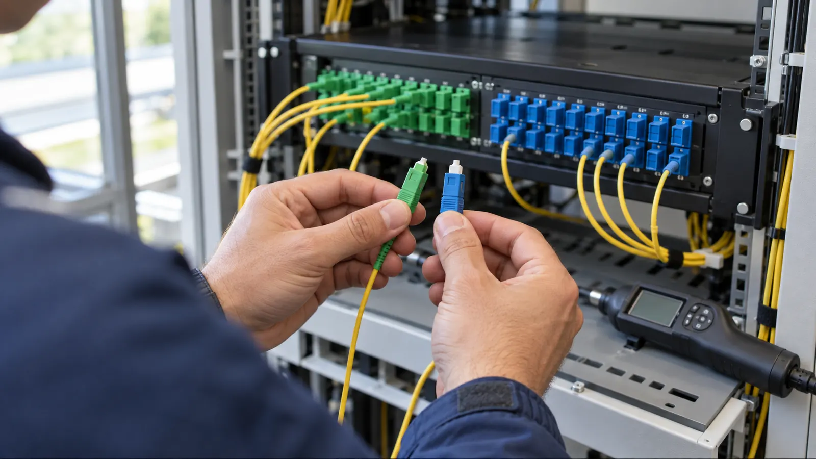
A patch cord can latch into an adapter and still make the wrong optical connection. Connector shape gets attention on a bill of materials; end-face polish can disappear into a shorthand note. We treat that missing detail as a design issue because a replacement cord must match the glass it touches.
APC and UPC describe different physical-contact finishes. Both can carry a useful signal with low insertion loss when the interfaces are compatible and clean. The choice becomes consequential when reflected light returns toward a source or interferes with the received signal.
We compare the polish first, then follow it through the port schedule and acceptance record. That sequence gives an access-network designer and an enterprise network owner different answers for sound reasons, without turning connector color into a substitute for an interface specification.
APC vs UPC: end faces and reflected light
The apc vs upc difference is the connector end face: APC uses an 8-degree angled physical-contact polish, while UPC uses a non-angled ultra physical-contact polish. APC directs more reflected light away from the guided return path; selection also depends on equipment compatibility and the specified optical acceptance limits.
The ferrule holds the geometry
The ferrule positions the fiber so its core aligns with the opposing core. UPC has a curved physical-contact surface centered about the fiber axis; calling it flat is convenient shorthand, but it can mislead someone into picturing an air gap between planar ends. APC adds an intentional angle to that contact geometry. Both need physical contact.
IEC 61755-3-2:2024, edition 2.0, published April 11, 2024, covers connector parameters for dispersion-unshifted single-mode physically contacting fibres with angled 2.5 mm and 1.25 mm cylindrical full zirconia ferrules. Its optical interface uses an 8-degree polish. We specify the applicable interface rather than assuming every connector described as angled has interchangeable geometry.
Housing and polish are separate choices. SC and LC identify connector families; APC and UPC identify the end-face treatment. A drawing that says only LC leaves the polish unresolved. We keep both descriptors on the port schedule, including the equipment-facing connection, where an otherwise consistent patching scheme may need a different termination.
Read the sign before comparing decibels
Reflectance compares returned optical power with incident power and is normally expressed as a negative decibel value. Return loss expresses the inverse ratio as a positive value. Lower reflectance is better. Higher return loss is better. We preserve those signs in acceptance tables because reversing the inequality reverses the pass condition.
For a mathematical example, reflectance of -50 dB corresponds to return loss of 50 dB for the same isolated reflection and reference conditions. A -60 dB reflection returns one-tenth as much power as a -50 dB reflection. These are ratio examples, not universal acceptance thresholds assigned to UPC and APC.
IEC 61300-3-6:2008, edition 3.0, published December 9, 2008, addresses fibre interconnections and passive components in Basic test and measurement procedures, Part 3-6: Examinations and measurements, Return loss. It defines return loss using incident and reflected power and provides measurement procedures. We use that distinction when reviewing a connector result against a whole-link report.
Insertion loss measures transmitted power reduction. A connector may meet its insertion-loss limit and still exceed its reflectance limit, so we do not approve a substitution from the loss column alone. The APC label does not promise lower insertion loss than every UPC assembly, and a dirty angled connector can perform poorly.
Why APC is the norm in PON and RF video paths
APC suits passive optical access networks because its angled interface helps control reflected light in a bidirectional optical path. A PON shares feeder infrastructure through passive splitters, and an unwanted reflection can travel back through that distribution system toward active equipment. We therefore carry the operator's reflection requirements into the connector schedule before choosing patch assemblies.
Reflection control across the PON tree
The Fiber Optic Association's Network Troubleshooting reference identifies multipath interference from reflective connections as a possible source of network impairment. APC addresses the reflection mechanism at a connector. It does not restore power consumed by splitter loss. Our GPON architecture and split-ratio guide explains the distribution choices that must be evaluated alongside connector performance.
| Design question | APC | UPC |
|---|---|---|
| End-face geometry | Angled physical contact, commonly 8 degrees | Non-angled, curved physical contact |
| Reflection behavior | Angle reduces coupling of reflection into the guided return path | Residual reflection can couple back toward the source |
| Common application | PON access and reflection-sensitive RF video paths | Many enterprise and data-center equipment interfaces |
| Single-mode color convention | Green is a recognition aid | Blue is a recognition aid |
| Direct mating | Mate with a compatible APC interface | Mate with a compatible UPC interface |
| Acceptance basis | Specified loss and reflection limits, verified by testing | Specified loss and reflection limits, verified by testing |
Consider a proposed access cabinet with connectorized splitter outputs and a replaceable subscriber jumper. This is a design example, not a reported project. We would identify the polish on both sides of each adapter and follow the jumper to the subscriber terminal, rather than approving it because the cabinet's front ports are green.
A shared optical plant also makes substitutions consequential beyond the immediate work area. If a field replacement changes the connection's reflection performance, a received-power reading at the subscriber does not establish that every affected operating condition remains acceptable. Our design review keeps the equipment interface requirements attached to the passive plant records.
Analog RF video makes reflections especially important
An RF video overlay transports an analog signal over an optical carrier, where reflected optical energy can contribute to noise or distortion. Low reflection matters directly. That sensitivity explains APC's established role in these paths, even when the digital access service sharing the infrastructure appears to work with an inferior connection.
We retain the overlay's own acceptance requirements when video and data coexist. Passing a digital service check cannot establish analog video quality, and an optical power measurement alone cannot characterize every reflection-related impairment. The project specification should identify the operating services before it defines which measurements constitute acceptance.
The limitation of our preference for APC in access plant is the added interface discipline when equipment ports require UPC. Mixed inventories need explicit separation. At that boundary, our FTTH design work aligns the equipment schedule with the patching details so a crew can select the correct assembly without interpreting a general note.
Where UPC remains the right enterprise interface
UPC fits many enterprise and data-center links because the equipment and patching ecosystem already specify non-angled interfaces with adequate reflection performance for the application. Compatibility leads the decision. We retain UPC where the optical interface requires it, even if APC is the default elsewhere in the owner's network.
Let the equipment port set the mating requirement
ANSI/TIA-604-10-D, FOCIS 10 Fiber Optic Connector Intermateability Standard, Type LC, was announced as released by TIA on March 10, 2025. Revision D adds an informative annex addressing dual duplex LC belly-to-belly pitch and latch dimensions for active-device receptacles. It illustrates the mechanical detail behind a family name; it does not make every LC optical interface equivalent.
We distinguish a connector's mechanical fit from the optical interface accepted by the equipment. The approved port specification must identify the required termination and applicable optical performance. Where a panel connects to a UPC equipment port, a correctly specified UPC cord is the straightforward choice. An angled plug cannot improve an incompatible receptacle.
An enterprise equipment room provides a useful design example: a patch panel terminates the building fiber, and a removable equipment cord connects that panel to an optical transceiver. We review the two mating interfaces independently. The panel's documentation must describe its rear termination too, because the visible adapter shell alone cannot establish what glass sits behind it.
Data-center location does not guarantee UPC
A facility label cannot select the polish. Some optical applications inside data centers require angled interfaces, including particular parallel single-mode implementations, so we check the actual optical specification before extending a UPC convention across a room. The same discipline applies when an existing duplex link is replaced with a different optical architecture.
Our recommendation for compatible UPC links is conservative: retain the interface and verify its performance against the application. Changing all connectors to APC creates a migration task without proving a service benefit. We would require a documented reflection problem or a changed equipment requirement before recommending that conversion to an owner.
Inventory decisions should follow the accepted drawings. If a maintenance group stocks both finishes, its descriptions need enough detail to distinguish the complete assemblies, and replacement approval must preserve the interface at each end. We put that responsibility into the handover discussion so an equipment change does not quietly invalidate the patch schedule.
What happens when APC and UPC are mated
Direct mating puts unlike contact geometries together. The angled surface and non-angled surface cannot establish the intended fiber-to-fiber contact, which can introduce excess loss and reflection and can damage the end faces. The Fiber Optic Association explicitly warns against mixing them. Do not force the connection.
An adapter cannot change the polish
A passive mating adapter aligns compatible ferrules; it does not reshape their ends. Some housings allow a mismatched pair to engage mechanically, making a latch click poor evidence of optical compatibility. We verify both connectors before mating. Green and blue are useful single-mode recognition cues, but written identification must settle any uncertainty.
A hybrid patch cord is different. A continuous fiber can have APC at one end and UPC at the other, provided each end mates with the matching interface at its destination. No APC face touches a UPC face in that arrangement. We label both ends and preserve that distinction in the bill of materials.
Inspect the hidden side. Before replacing a jumper at an adapter panel, verify the rear connector's polish from the approved record or a controlled inspection. The front adapter color cannot confirm an undocumented rear termination.
After a suspected mismatch, isolate the affected connection using the owner's service procedure and inspect both ends with appropriate equipment. Do not look into a fiber. Cleaning can remove contamination, but it cannot repair a damaged polish; replace a damaged termination and repeat the required optical tests before accepting the repair.
A field test lead can create the same problem as a service jumper. We specify the polish at the instrument port separately from the polish facing the cable under test, and we check the receive lead as carefully as the launch lead. Otherwise, the test setup can introduce the defect it is supposed to measure.
APC vs UPC in specifications and test acceptance
The specification should let a reviewer distinguish a wrong connector from a bad measurement. We start with the mating interfaces, then define performance at the relevant reference planes. A general instruction to use low-loss fiber connectors leaves the return path and the acceptance boundary unresolved.
Make the port schedule explicit
Our recommended schedule identifies connector family and polish at each interface, with the corresponding fiber and assembly description. A hybrid cord receives a separate end designation. Name both destinations. A procurement reviewer should be able to compare the offered assembly against that schedule without relying on a photograph or interpreting a color abbreviation.
Write the performance limits separately. State maximum insertion loss for the specified connection or link, maximum connector reflectance where required, and minimum optical return loss for the defined plant segment. Include test wavelengths and direction. We require the owner to resolve missing numerical thresholds before procurement rather than letting the tester's default profile become the contract.
Return loss for a plant segment includes the optical energy returning from that segment, including distributed backscatter. It cannot simply be substituted for the reflectance of its worst connector. Reference planes matter. A report must identify what was included in the measurement so the acceptance reviewer can compare like quantities at the same boundary.
For an illustrative equipment boundary, write the cord as SC/APC at the distribution panel and LC/UPC at the equipment port, with each end matched to its own receptacle. The schedule must also identify the fiber type. We would reject an order line that reduces that description to a fiber jumper, because a purchasing substitution could preserve the length while changing the optical interface.
Separate inspection from optical qualification
IEC 61300-3-35:2022, edition 3.0, published September 16, 2022, covers Visual inspection of fibre optic connectors and fibre-stub transceivers within its basic test and measurement procedures series. It addresses debris and surface defects and explicitly separates visual inspection from optical performance qualification. A clean inspection image therefore supports acceptance but cannot replace loss or return-loss measurements.
IEC 61280-4-2:2024, edition 3.0, published May 6, 2024, is Fibre-optic communication subsystem test procedures, Part 4-2: Installed cabling plant, Single-mode attenuation and optical return loss measurements. It addresses installed single-mode plant, with principles applicable to branching and wavelength-selective passive devices. We use the chosen procedure within its scope and document how the actual plant is connected for testing.
An optical time-domain reflectometer, or OTDR, helps locate events; an end-to-end loss test measures transmission loss across the referenced path. They answer different questions. Our OTDR testing and splice-loss acceptance guide explains why the event record needs review alongside the link result, especially when an apparent splice or connection value invites a premature pass.
Test settings affect visibility. We require a launch and receive arrangement that allows the connections under review to be evaluated, with instrument range and resolution suited to the path. When a reflection is below the instrument's measurement capability, the report should state that bound instead of assigning an invented precise value.
The closeout record should connect every result to its fiber and port designation. We retain the test configuration so a failed result can be investigated without guessing which cord was used. Where a repair changes the installed assembly, update the as-built record and preserve the retest as the evidence for acceptance.
An unresolved OTDR event needs a qualified result. If adjacent connections fall inside the event dead zone, we require a suitable test arrangement or another accepted measurement method before assigning a separate connector value. Shortening the pulse can improve resolution but reduces available measurement range. The acceptance record should explain that choice so a grouped event cannot be mistaken for proof that each connection passed separately.
Choose the interface for the application
PON and RF video owners: Specify APC for the reflection-sensitive passive interfaces required by your network design, and make every equipment exception explicit. Keep the reflection limits visible through acceptance. We would reject a UPC substitution justified only by a passing optical power reading, because that reading does not establish equivalent reflection behavior.
Enterprise and data-center operators: Keep UPC on interfaces designed for UPC and qualify the completed channel against the equipment's requirements. Follow the port specification. For a new optical architecture, review its connector requirements afresh rather than extending an existing patch-room convention into a different application.
Design and maintenance teams: Document mixed-polish boundaries using correctly terminated cords and matching local interfaces. We recommend a port-level review before the assembly is ordered, followed by inspection and the specified optical tests after installation. Our partner and company information identifies the people responsible for Draftech International's delivery work.
Draftech International keeps engineering 100% in-house and delivers full turnkey construction through Draftech-managed subcontract crews. We connect the patch schedule to the acceptance package so missing polish notes and ambiguous test boundaries are resolved together. Use our contact page to discuss a fiber design package or send the interface questions to info@draftech.com.
For a qualifying route, Draftech engineers the first 20,000 linear feet at no cost, from feasibility and field survey through permit approval. Our free route engineering offer gives an owner a way to address the route design while connector and acceptance requirements are being defined; the owner reviews each request before Draftech commits the package.