Passive optical network meaning: the shared fiber path
A passive optical network is a fiber access system that connects 1 provider-side optical line terminal to multiple customer terminals through unpowered optical splitters. The passive optical network meaning rests on that shared distribution path: the fiber and splitters carry light between powered endpoints without an electronic switch at each branch.
The word passive can cause trouble in a service discussion. A buyer hears it and pictures a connection that keeps working without electricity anywhere. The network operator means something narrower: the branching optical plant needs no electrical supply to divide the signal. We start with that distinction because it explains both the attraction of PON and the equipment that still needs backup power.
The endpoints need power. An optical line terminal, or OLT, sits on the provider side, while an optical network terminal, or ONT, terminates the connection at the subscriber. Between them, the optical distribution network, often shortened to ODN, contains the fiber path and passive components. RFC 6456, Multi-Segment Pseudowires in Passive Optical Networks, published in November 2011, describes these endpoint and distribution-network roles.
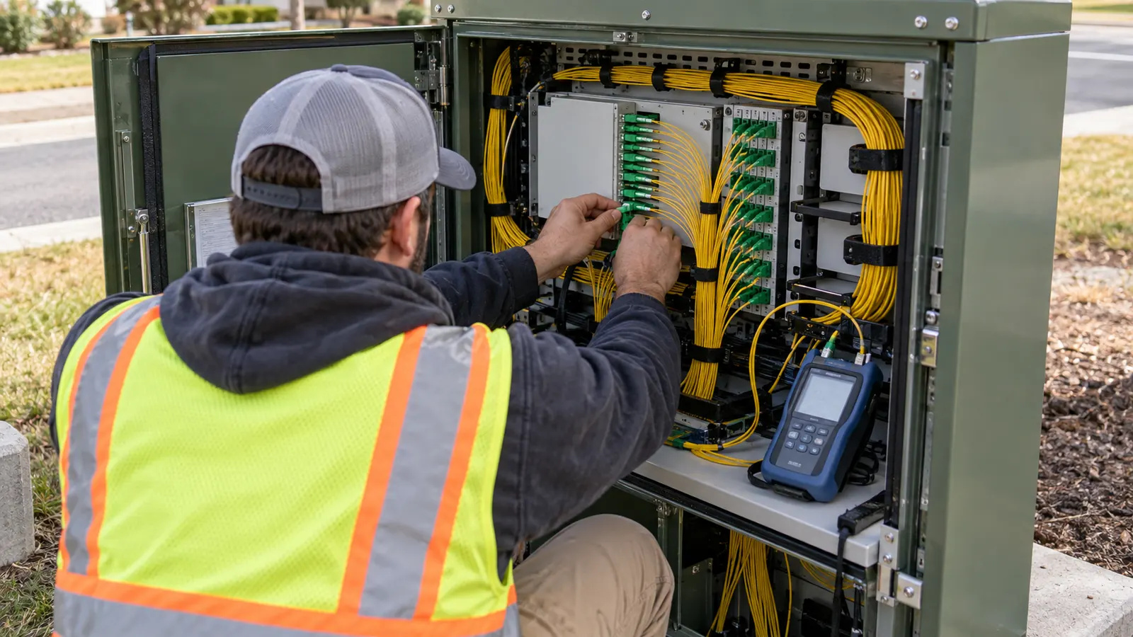
We find a connection sketch more useful than a photograph of a cabinet when explaining the term. A cabinet can contain several kinds of equipment, and its outer shell says little about what happens inside. Follow the fiber instead. When a shared feeder reaches a passive splitter and branches toward separate subscribers, the drawing begins to show the defining PON arrangement.
PON and FTTH describe different things
PON describes the access architecture. Fiber to the home, or FTTH, describes where fiber reaches. A home can receive fiber through a PON architecture, but the words FTTH alone do not identify the equipment or tell you whether an optical splitter sits upstream. We keep those terms separate when reading a scope because each answers a different question about the connection.
For a reader moving from terminology to route delivery, our explanation of what FTTH design includes covers the wider engineering package. Here, we stay with the network's parts and how they relate. Knowing the meaning of PON lets you read a proposal more accurately; selecting equipment and preparing construction drawings require information about the actual route and service requirements.
From the OLT to the subscriber
A PON branch starts at an OLT port. The OLT connects the access network to the provider's upstream network and coordinates communication with the customer terminals assigned to it. A chassis may carry multiple PON ports, so the word OLT can refer to much more equipment than the single shared branch shown on a simple diagram. We distinguish the chassis from the port whenever a drawing discusses capacity.
Feeder fiber carries the shared connection
The feeder is the fiber path between the provider-side equipment and the splitting location in a basic centralized arrangement. It may pass through splice points or patch panels before reaching the splitter. Those connections do not turn it into a different architecture. What matters for the definition is that the feeder carries the shared optical connection toward the point where the paths separate.
A cable holds individual fibers. They are different counting units. A drawing can show one feeder cable serving several splitter inputs through different fibers, which is why we avoid interpreting a cable line as a single PON port without reading its annotation. The route on the map and the logical connection on the schematic describe related things, but they need different labels.
A splitter divides optical power
A passive optical splitter divides incoming light among its output paths. Cisco's Understand GPON Technology, document 216230, updated December 6, 2023, describes a 1:32 splitter arrangement: one input serving thirty-two output paths. That ratio describes the branching arrangement. It does not tell you how many subscribers have ordered service or how many output ports are currently connected.
Splitting introduces optical loss. It cannot amplify light. The receiver at the far end must still receive a usable signal after the complete path has reduced its strength, including the splitter and the intervening fiber connections. We treat the ratio as useful vocabulary here, rather than recommending it for an unspecified route; the appropriate arrangement depends on engineering that a definition cannot supply.
The splitter does no packet switching. It has no forwarding table that chooses a customer according to an internet address. In the downstream direction, the optical signal is distributed across its branches, while the endpoints perform the protocol functions needed to deliver traffic correctly. That difference explains why replacing a field switch with a splitter changes more than the power connection in the enclosure.
| Component | Position | Function |
|---|---|---|
| OLT | Provider endpoint | Coordinates shared access |
| Feeder | Before split | Carries shared light |
| Splitter | Branching point | Divides optical power |
| Distribution | After split | Reaches customer serving points |
| ONT | Subscriber endpoint | Terminates optical access |
Distribution fiber and the final drop
Distribution fiber carries the connection onward from the splitting area toward customer serving points. The drop completes the connection to a particular premises. Naming boundaries can vary between operators, especially when splitters are spread across the network, so we recommend reading the drawing legend before assuming that every segment called distribution has the same starting point in every project.
The physical route still needs ordinary care. Cable protection and accessible enclosures matter even when the optical components inside use no electricity. A passive branch can be damaged by construction or an unsuitable bend, and a dirty connector can impair the optical path. We therefore read passive as an operating characteristic, never as a promise that the outside plant needs no maintenance.
The ONT ends the optical access connection
The ONT receives the downstream optical signal and provides the subscriber-side service interface, often Ethernet. It also transmits upstream toward the OLT. The term ONU, or optical network unit, appears in standards and equipment documents as the broader term; ONT commonly identifies the unit that terminates fiber at the subscriber premises. Equipment literature may use the names differently, so the stated function matters.
An ONT may be separate from the router. Integration varies by product. When they are separate, a working optical connection can coexist with a problem in the customer's router or wireless coverage, and replacing the outside fiber would not address that fault. We keep the optical termination distinct from the home network when explaining where the provider's access connection ends and where indoor connectivity begins.
Why the passive part still needs active control
Passive components carry the light; powered terminals control communication. In GPON, downstream traffic travels from the OLT toward the ONTs, and upstream traffic moves in the opposite direction. Cisco document 216230 describes downstream broadcast and upstream time-division multiple access. The OLT assigns upstream transmission opportunities so the customer terminals can share the return path without transmitting over one another indiscriminately.
Sharing happens in both directions
A splitter cannot schedule a transmission. The OLT does that. We explain the division this way because a branch drawing can otherwise make the network look like a set of independent dedicated links. The customer fibers separate after the split, but they still lead back to a shared PON interface whose operation depends on coordinated access to the optical medium.
Shared capacity also needs careful wording. A line rate belongs to the PON interface, while a subscriber's purchased service has its own provisioned rate and conditions. Dividing the line rate by the splitter output count produces arithmetic, not a service guarantee. Actual delivery depends on the access equipment's configuration and demand, and the rest of the provider network can also constrain performance.
We recommend asking what a quoted speed describes before comparing offers. Is it the optical line rate or the service delivered at the subscriber interface? The distinction changes the meaning of the number. A proposal that labels both clearly gives the reader a fair basis for discussion without implying that each connected ONT owns the entire shared channel all the time.
Read the label beside the number. When a proposal says 1:32, ask whether it identifies splitter outputs or connected ONTs. The first is a component characteristic; the second requires records of how that component is used.
A passive path can still have a common failure
The shared feeder is a common dependency. If it is interrupted, downstream subscribers on that path can lose their connection together, even though each has a separate drop. A drop fault affects a different part of the tree. We use that distinction to explain why the location of a fault matters more than the fact that the network is described as passive.
Endpoint power remains essential. An unpowered ONT cannot continue normal service merely because its splitter has no electrical connection. The OLT also depends on its own supply. Backup arrangements belong to the particular installation, and a reader should not infer their duration or coverage from the acronym PON; the equipment and power provisions have to state those details separately.
Centralized and distributed splitting
Centralized splitting places the splitting stage together at a common serving location, while distributed splitting spreads stages through the serving area. Cisco's What Is Passive Optical Networking (PON)? describes these deployment approaches. Both retain passive branching. The distinction concerns where the split occurs and how the fibers connect, rather than whether the network qualifies as PON at all.
Centralized splitting keeps the branches together
A centralized arrangement makes the common splitting point easy to recognize on a schematic. The feeder reaches that location, and output paths extend toward the subscribers it serves. We prefer this picture for a first explanation because the reader can see the shared side and the separated side without following a second branching stage through another part of the drawing.
That teaching preference has a limitation: a tidy centralized diagram can hide the amount of distribution fiber and enclosure space the real serving area requires. The map still matters. A common splitter location that looks convenient on paper may be awkward to access or poorly placed for the actual customers, so a clear explanation should never become an automatic recommendation for centralized construction.
Distributed splitting branches in stages
A distributed arrangement can place an initial splitter upstream and additional splitters farther into the serving area. As an illustrative count, a 1:4 stage feeding four 1:8 splitters has thirty-two final outputs: four multiplied by eight. This is a topology example, not a selected configuration. It demonstrates why a final output count alone cannot tell you how many splitter locations a connection passes through.
The stages change what a reader must follow. We would trace a customer path through each splitter it uses, rather than stopping at the first branch symbol and assuming the rest is direct fiber. Two arrangements with the same final output count can have different physical routes and access points, which is why their drawings should identify the stages explicitly.
Follow one subscriber path. In a distributed drawing, trace a single ONT back to its OLT port before counting the whole serving area. That makes intermediate splitters visible and prevents a final output count from disguising the connection's actual sequence.
We carry that distinction into our FTTH design work, where the logical branch must correspond to a buildable route. The definition gets a buyer far enough to understand the options. Choosing between them requires the serving-area layout and the operator's requirements, rather than a universal claim that one arrangement always needs less fiber or is easier to maintain.
GPON and XGS-PON are kinds of PON
PON is the family name. GPON and XGS-PON identify particular systems within it. Both use a passive distribution path between active endpoints, but their interface specifications differ. We keep the family name separate from the system name so that a statement such as PON-ready does not get mistaken for a complete equipment compatibility or service-capacity specification.
GPON: gigabit-capable passive optical networking
ITU-T G.984.2, Gigabit-capable Passive Optical Networks (G-PON): Physical Media Dependent (PMD) layer specification, approved August 29, 2019, is the in-force physical-layer recommendation. The familiar GPON rate pair is about 2.488 Gbit/s downstream and 1.244 Gbit/s upstream. Those are shared optical line rates; they should remain labeled that way when they appear beside a subscriber service offering.
GPON gives the reader a more precise description than PON alone, but it still leaves engineering choices open. We would expect a technical proposal to identify the actual OLT and compatible terminal equipment instead of relying on the acronym as a compatibility promise. For the deeper questions about optical loss and network layout, continue to our GPON network design guide.
XGS-PON: symmetric 10-gigabit-class access
ITU-T G.9807.1, 10-Gigabit-capable symmetric passive optical network (XGS-PON), approved February 22, 2023, with Amendment 1 approved in May 2025, defines the symmetric system. Its nominal line rate is approximately 10 Gbit/s in each direction. Symmetric refers to equal upstream and downstream line rates. It does not, by itself, establish the throughput that a particular customer device will receive.
The higher rate changes capacity discussions. It does not remove the splitter. We would still ask how the branch is shared and what service the operator intends to deliver, particularly when an equipment description is being used to justify a retail speed claim. Matching the service requirement to the system is a separate question from recognizing that both GPON and XGS-PON belong to the passive optical family.
Passive optical network meaning in an upgrade discussion
Existing fiber may remain useful during a system upgrade, but the word passive does not certify that every installed component is suitable. Compatibility and optical loss must be evaluated for the intended system. We recommend treating reuse as an engineering question: a familiar cabinet or unchanged cable route alone cannot establish that the replacement endpoints will communicate successfully across the complete existing path.
For the optical-loss part of that discussion, the free PON Power Budget Calculator checks whether a GPON or XGS-PON link closes against the ITU-T class budget, covering total OLT-to-ONT loss, margin and maximum reach. Its purpose is specific. We use a budget check to examine the optical path, while equipment compatibility and the customer's service definition remain separate questions.
Recommended next steps for when the conversation moves beyond definitions
For a service buyer: ask the provider to distinguish the PON system's line rate from your provisioned service rate. Confirm where the service is handed over. That gives you a clear point at which to discuss performance and avoids treating an ONT's optical capability as a promise about wireless coverage throughout the building.
For an infrastructure owner: request a connection schematic that identifies the serving OLT port and shows the splitter stages along a customer path. We recommend this before debating centralized versus distributed labels because the schematic reveals the arrangement being proposed. A route map then explains where that arrangement sits physically, without requiring every commercial reader to interpret a full construction package.
For a project manager: put unresolved terminology into the scope before requesting a delivery commitment. If a proposal uses ONT and router interchangeably, or leaves the splitting location unclear, ask for those boundaries to be stated. Our partner and company information identifies the people behind Draftech's delivery model, and the contact page provides a direct route for discussing a defined project scope.
Unclear endpoint responsibilities and missing splitter locations become practical problems when a route moves into delivery. Draftech International provides turnkey telecom and power infrastructure from field survey through planning, construction drawings, permits, agency coordination, construction, as-builts and closeout. Our engineering is 100% in-house; full turnkey construction is delivered by Draftech-managed subcontract crews. For a fiber owner, that connects the proposed optical arrangement to the route documentation and accountable delivery team.
If your next step is to turn a proposed fiber route into an engineering package, our free design offer covers the first 20,000 linear feet of a qualifying route at no cost, from feasibility and field survey through permit approval. The owner reviews each request before Draftech commits the package, so send the route and intended service area for that review.