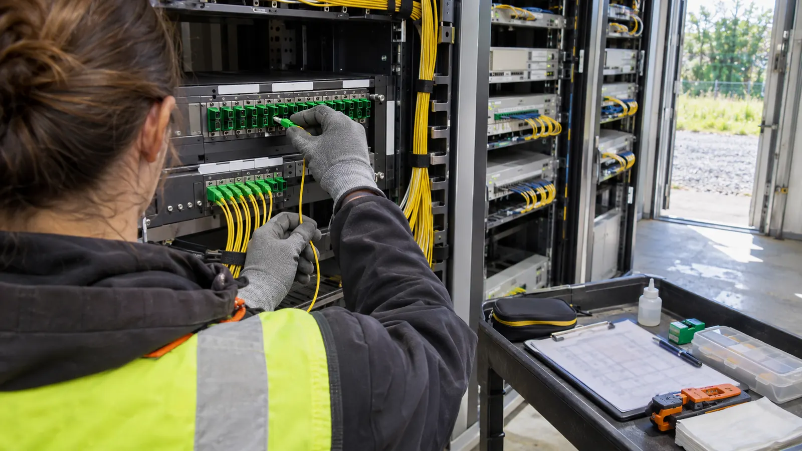
- What open access networks ask of the owner
- Compare passive and active wholesale before assigning fibers
- Reserve fiber counts that remain usable end to end
- Place handoffs and hubs around access requirements
- Keep open access networks traceable by tenant
- Recommendations for the design package by reader type
What open access networks ask of the owner
Open access networks use one owner's fiber infrastructure while separate providers sell service over it. The Open Fibre Data Standard's scope primer describes 3 layers: passive infrastructure, active infrastructure and services. For planners, the design question is where those responsibilities meet and what physical capacity remains available when another provider needs access.
A shared route can support different retail offers without giving every provider the same physical connection. That distinction belongs in the design brief. A provider leasing dark fiber needs a continuous optical path to its equipment, while a provider buying a lit service needs an agreed handoff from the network operator. The asset being handed over sets our design starting point. The ownership label comes afterward.
The infrastructure owner builds and holds the physical network. The network operator runs the active equipment that carries traffic. Service providers sell the end-user connection and manage their retail relationship. Those roles can sit in separate organizations, or the owner can also perform the operator role while independent providers sell services. The division of responsibility belongs on our drawings, including who controls the equipment at each boundary.
Ownership extends beyond municipalities. Utilities can hold fiber infrastructure, cooperatives can build a shared network, and private companies can own wholesale plant without selling retail service themselves. City-specific ownership choices belong in our discussion of municipal broadband. The physical design still has to show how a provider reaches the premises it intends to serve, regardless of the owner's legal form.
Access must reach the intended customers. A route passing an address does little for a provider if its assigned strands terminate at a hub where that provider has no usable connection. Serving-area boundaries therefore need to follow the proposed access arrangement, and our HLD should expose any area that requires a different handoff. This is especially useful where an existing backbone feeds new distribution plant with a different allocation method.
A design review should separate ownership from use. The owner may retain a cable while allocating only selected strands to a tenant, and a shared enclosure may contain circuits that belong to different parties. That distinction should be settled before our fiber plan is labeled. Otherwise, the same word, such as available, can mean spare to the designer and already reserved to the owner.
Compare passive and active wholesale before assigning fibers
Passive wholesale gives a provider access to physical infrastructure, such as fiber or duct. Active wholesale gives the provider a lit service through the operator's equipment. OECD's Next Generation Access Networks and Market Structure describes wholesale wirelines as Layer 1 open access, including passive wirelines and ducts. That distinction helps our design team locate the physical boundary rather than infer it from a retail service description.
Passive wholesale: preserve a usable optical path
A passive fiber arrangement requires enough continuity for the provider's chosen architecture. The design must show where leased fibers begin and end, and whether an intermediate patch or splice is part of the agreed path. Duct access has a different boundary: the available pathway must accommodate the provider's cable under the owner's installation requirements. Duct occupancy requires a separate review from our fiber allocation.
The optical path still needs qualification. ITU-T G.652 (2024) describes single-mode fiber with a zero-dispersion wavelength around 1310 nm; that fiber designation identifies transmission characteristics, not the loss of an installed route. A provider receiving dark fiber needs the route's actual connectivity and acceptance information. Keep the distinction visible. A cable specification alone cannot establish whether the finished path supports the proposed equipment.
Passive access suits providers that need control of their own active equipment. That control also creates physical obligations at the handoff, because the equipment needs a place to connect and the assigned fibers need a documented destination. Our preferred passive arrangement has a limitation: reserving accessible strands can leave usable capacity idle until demand develops. The owner should accept that trade-off deliberately rather than discover the reservation after allocation.
Active wholesale: define the lit-service boundary
An active arrangement can let multiple retail providers share the operator's access equipment. Provider separation then depends on the operator's service architecture rather than a dedicated strand for every retail provider. ITU-T G.9807.1 (2023, amended 2025) specifies XGS-PON's nominal line rate as 9.95328 Gbit/s in each direction. That is an access-system rate, not a promise that every customer or retail provider receives that rate continuously.
The designer needs the service interface. The operator should identify its handoff location and the equipment footprint that the site must accommodate, even when the retail provider has no equipment in the neighborhood hub. Those supplied requirements become the basis for our physical layout. The owner and operator remain responsible for defining the wholesale service and its operating arrangements.
The comparison below follows those boundaries into the drawings. Its purpose is to identify which assumptions must be settled before a fiber count or hub layout can be accepted.
| Design decision | Passive wholesale | Active wholesale |
|---|---|---|
| Access delivered | Fiber path or duct access | Lit service at an agreed interface |
| Active equipment | Provider equipment needs an identified connection point | Operator equipment serves the access network |
| Fiber allocation | Reserve the physical paths required by each arrangement | Size shared plant around the operator's architecture |
| Handoff space | Allow for provider termination and agreed equipment | Allow for operator termination and provider interfaces |
| Records | Trace tenant rights to physical assets | Relate physical assets to operator-supplied service references |
Reserve fiber counts that remain usable end to end
A spare strand earns its place only if it can reach the intended handoff. The Fiber Optic Association's Fiber Optic Cable Color Codes explains the 12-color sequence used to identify fibers and buffer tubes. Identification supports allocation, but the sequence does not prescribe cable size or a spare percentage. The serving architecture and the owner's stated expansion assumptions should drive our count.
Start at the serving-area boundary and work toward the handoff. For a passive arrangement, trace the provider's required path through every cable segment that carries it; for an active arrangement, trace the operator's feeders through the selected splitter architecture. Count the bottleneck. Spare distribution fibers cannot compensate for an exhausted feeder segment upstream, even when the total fiber count on the route appears generous.
Keep growth reserve distinguishable from restoration reserve. A strand held for an added provider can disappear from the expansion plan if it becomes a repair path and no replacement allocation is recorded. The reason for each strand reservation belongs in our design notation, with authority to release it identified. That lets the owner review a proposed reassignment against the original purpose rather than against a single aggregate spare count.
Provider growth also needs a location. Reserving fibers near one handoff does not help a tenant that requires access at a different colocation point unless the route between those locations remains available. This is why our node placement review belongs beside the count schedule. The drawings should make the proposed connection practical without assuming that another tenant's allocated path can be moved to accommodate it.
A count review should distinguish dedicated paths from shared distribution. The choice between point-to-point fiber and PON changes where fibers are shared and where a provider can obtain physical access. Neither topology establishes open access by itself. The selected access model must explain how the owner will make the chosen topology available to separate providers.
Our recommendation is to record the expansion assumption alongside the initial allocation, then check continuity through the proposed splice arrangement before accepting the HLD. This keeps a future provider reservation visible when the design moves into LLD, where a locally convenient splice can otherwise consume the path the owner intended to preserve.
Check the destination: Follow reserved fibers to the actual handoff panel before counting them as available for another provider. A spare that stops at an intermediate closure needs a defined onward path.
Place handoffs and hubs around access requirements
Handoff placement determines how much of the shared plant a provider can reach. It also determines where patching changes are concentrated. Our fiber network design work connects those physical requirements to the design package, with fiber counts and node placement resolved together. An owner should be able to point to the boundary on the plan and understand which side supplies each connection.
Handoff and colocation space
A lit handoff must match the operator's selected interface, and its rate must be distinguished from the access system behind it. The 9.95328 Gbit/s rate in ITU-T G.9807.1 describes XGS-PON transmission; it does not specify a provider's separate aggregation handoff. The operator's actual interface requirements need to reach our design team before termination space is assigned. Rate alone cannot size the room.
For passive access, show the demarcation panel and the route from that panel to the provider's agreed equipment location. Colocation space needs a workable cable path, not merely an empty rectangle on a floor plan. Equipment access should remain possible when adjacent positions are occupied, and the proposed installation should not require technicians to disturb another tenant's connections during routine patching.
Physical separation should be clear to a visiting technician. Shared racks may be appropriate, but the drawing needs to identify which termination positions are assigned and which remain reserved. Our layout review should also distinguish a passive cabinet from a powered equipment site, because placing provider electronics in an enclosure changes the facilities requirements. An unused splitter slot cannot be treated as an equipment position.
Splitters and hub capacity
Splitter placement can either concentrate reassignment at a hub or distribute it into field enclosures. The Fiber Optic Association's guide to testing optical couplers explains that an equal split in half reduces power by 3 dB before excess loss. That relationship matters when considering additional splitting to serve another area: physical room for a splitter does not establish optical margin for the new path.
Centralized splitting can provide a clear patching location, while distributed splitting can place part of the allocation deeper in the network. The owner's physical access needs and selected optical budget determine our preferred splitter placement. Choose the access boundary first. A distributed layout that serves the initial operator neatly can make later passive access awkward if the required strands are already shared beyond reach.
Room for future connections must survive the installed arrangement. Review cable entrances and patch management against the reserved termination positions, rather than assuming that unused panel capacity remains reachable after the first tenant's cords are dressed. Our fiber distribution hub sizing discussion addresses the enclosure capacity side of that decision. The open access requirement adds the need to preserve access for the intended provider arrangement.
Review the occupied layout: Evaluate the next equipment position with the initial connections drawn in place. This exposes a blocked cable path before an empty-space allowance becomes an unusable reservation.
Keep open access networks traceable by tenant
A tenant reference should lead to a physical path that someone can verify. The Open Fibre Data Standard's network schema describes a span through its 2 endpoint nodes, using start and end identifiers. That is a useful connectivity model, although tenant-level strand allocation requires more detail than a route map. The records in our GIS-format as-builts should preserve the relationship between the installed asset and the allocation information supplied by the owner.
The cable identifier needs to survive changes in tenant names. A provider may change its commercial identity or release an allocation without changing the underlying cable, so replacing an asset ID with the tenant name makes the physical record unstable. Keep those fields separate. The tenant can reference its assigned fibers while the asset retains an identity that remains meaningful throughout the record set.
Color is only part of identification. The FOA's 12-color sequence repeats in larger cable assemblies, which means a fiber color without its cable and buffer context can point to more than one strand. The splice record in our documentation should resolve that ambiguity. A tenant's path must remain traceable when it passes through cables that use different internal arrangements or different fiber counts.
Record the installed connection. Replace any planned patch that changed in the field. The as-built should connect the correct termination positions and identify the associated field revision, so a reviewer can tell whether the drawing describes intended work or installed work. That distinction matters when an apparent spare is already connected. A tenant allocation based on an obsolete design can assign the same path twice.
Acceptance evidence belongs to a path. A test file named only for the provider becomes difficult to interpret after that provider releases the fibers, while a stable physical reference can still identify the tested route. Our preferred record structure lets the owner follow an asset to its acceptance evidence and then determine which current allocation uses it. The evidence remains attached to the infrastructure.
Review record permissions separately. The owner may need a full network view while an individual provider receives only the information relevant to its allocation, but both views should refer to the same underlying assets. This is a documentation requirement to settle with the owner. It should not be left to a technician deciding which version of a drawing is safe to share.
Recommendations for the design package by reader type
City planners: Establish the physical boundary between the shared asset and the provider connection before accepting a serving-area map. The OFDS primer's 3-layer model helps separate the infrastructure decision from the service role. Require the proposed handoff to serve the stated area, so the design preserves the access arrangement the city intends to offer.
Utility and co-op planners: Protect the stated purpose of reserved capacity. Fibers retained for the owner's internal needs should remain distinguishable from tenant allocations, and any overlap must be an explicit owner decision. Give our designers that allocation basis before the cable schedule is finalized. Shared ownership of a route does not make every strand available for commercial use.
Private owners and ISP designers: Choose the wholesale boundary before selecting the final splitter arrangement. Providers requiring physical fiber access need reachable paths and suitable termination space; providers using a lit service need a defined operator handoff. Require the design package to show the chosen arrangement under occupied conditions. An initial layout should leave the next intended connection physically possible.
Draftech International's fiber network design service addresses disconnected reserves and crowded handoffs through HLD covering fiber counts, node placement, splitter architecture and serving-area boundaries, followed by LLD and GIS-format as-builts. Engineering is 100% in-house; the partners responsible for our work are identified publicly. The physical design package defines our scope here. Send the proposed access boundary and route information through our contact page or to info@draftech.com to discuss the design requirements.
For an eligible route, Draftech's free-design offer provides engineering for the first 20,000 linear feet. The owner reviews each request before Draftech commits the package. Bring the intended provider access points into that discussion so the qualifying route is considered with the physical connections it needs to support.