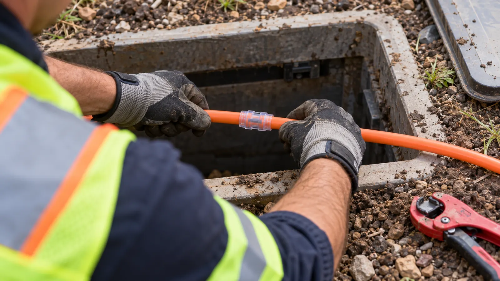
A spare pathway only helps if the next cable can travel through it. A bundle can look generous on a plan and still leave the owner with unusable capacity when a buried connection leaks or the receiving chamber forces a tight bend.
We start the choice between small tubes and conventional innerduct at the future cable installation. The civil design has to support that operation, even when the first construction package installs empty pathways and leaves the fiber decision open.
For an owner comparing methods, the useful question is how each system behaves after restoration. We look at expansion paths and access for repairs before choosing the duct arrangement. Both methods need disciplined construction.
What is microduct, and what does its size mean?
A microduct is a small conduit that provides a dedicated pathway for a compatible fiber unit or microcable. Dura-Line's MicroDucts HDPE data sheet lists a 14/10 mm size, identifying nominal outside and inside diameters. Bundles combine several pathways so an owner can install selected cables now and reserve others for expansion.
Read the bore before selecting the cable
The bore controls cable compatibility. The outside diameter controls how the tube fits into a larger conduit or a trench assembly, but it cannot tell us how much working space remains around a cable. We require both dimensions on the material schedule because a purchase description that says only "14 mm duct" leaves procurement without the bore information needed to check the proposed cable.
Dura-Line's MicroDucts HDPE sheet, identifier DL.MDHDPE.4.2023, also lists 5/3.5 mm and 10/8 mm products. Those labels describe different pathways, not interchangeable options. The sheet distinguishes nominal dimensions from minimum internal dimensions and separates products intended for an existing conduit from products suitable for direct burial. We check the selected part number rather than assigning a burial rating from size alone.
A cable that fits can still jet poorly. Its jacket and stiffness affect installation, and the approved combination must leave suitable airflow around the cable while passing through the actual route geometry. We use the cable manufacturer's compatibility guidance with the duct supplier's requirements. Fiber count alone cannot establish fit because cable constructions with similar counts can have different diameters.
Count individual tubes and usable destinations
Bundles place several color-identified tubes inside a shared assembly. Hexatronic's Microduct Assembly 5/3.5 mm product family, MPB30244+M, includes configurations with 4, 7 and 12 tubes. Those are catalog examples, not a recommendation for every route. The full assembly dimensions must fit the installation space, and a larger tube count does not remove the need for a compatible cable in each bore.
We assign a destination to every reserved pathway. A tube that ends before a future branch cannot serve that branch merely because it remains empty, and a continuous tube can lose practical value if its end is buried where a blowing machine cannot connect. Our design review follows spare tubes through the chambers, not just along the main route line.
Color helps crews identify tubes. It needs a record. At a branch, the selected tube should retain an unambiguous relationship to its upstream connection even if the assembly changes configuration. We want a technician opening the chamber later to determine which pathway reaches the required endpoint without disturbing an operating cable to find out.
Microduct bundles versus innerduct and pulled cable
Separate future capacity from initial fiber count
With a microduct system, the owner can install the pathway assembly first and populate selected tubes when cable is required. That separates the civil work from some future cable decisions. We favor this arrangement where planned branches have defined destinations and additional cables must remain separately accessible. Empty tubes need protection and acceptance testing just as occupied tubes do.
Conventional innerduct remains a strong option when the owner has selected the cable and wants a larger dedicated passage through an existing conduit. A pulled cable requires a tension and bend review suited to its construction, including how it enters and leaves each structure. Our comparison of HDPE and fabric innerduct develops that pathway decision beyond the small-bore systems discussed here.
The approaches overlap. A microduct bundle may itself be installed inside a larger conduit, while some larger cables can also be installed with air assistance. We compare complete systems rather than treating "blown" and "pulled" as fixed labels for every product. The table identifies the decisions that matter after the route has been selected.
| Decision | Microduct and air-blown fiber | Conventional innerduct and pulled cable |
|---|---|---|
| Future cable additions | Separate reserved tubes for compatible cables | Reserve a suitable larger passage or spare innerduct |
| Installation forces | Airflow with controlled feed for the approved system | Pulling tension and bend loading for the selected cable |
| Intermediate splices | Continuous cable can pass through duct couplings | Continuous pulls can also avoid unnecessary splices |
| Microtrench placement | Use a suitable assembly and approved transition detail | Check whether the larger pathway fits the civil section |
| Acceptance | Identify and verify every occupied or reserved bore | Verify passage and the installed cable as specified |
Preserve continuous cable where the route allows it
A pressure-rated duct coupling joins the pathway without joining the optical fibers. That distinction matters. When a compatible cable can pass through connected duct sections in a continuous installation, the network may avoid a splice that would otherwise be introduced to join separate cable lengths. We still place optical splices where the network architecture requires branching or termination.
Fewer splices are a possible outcome, not an inherent property of tubing. Reel length and installation access can require intermediate handling even when the duct remains continuous, and a change in installation direction needs a method that protects the cable. We do not delete a splice location simply because a supplier describes a long test installation under favorable conditions.
A real limitation of our preferred microduct approach is its dependence on keeping every future bore clean and sealed after the initial build. The owner inherits that maintenance obligation. Where the route is settled and no separate cable additions are expected, conventional innerduct with a suitable pulled cable can be the simpler operational choice. Spare capacity should serve a credible use.
How air-blown fiber travels through microduct
Match the installation method to the cable
Air-blown installation uses moving air to help carry a compatible fiber unit or cable through the tube. Jetting equipment commonly combines that airflow with controlled mechanical feed at the entry. The installer follows the equipment and cable instructions for the selected system; a light fiber unit and a larger jacketed microcable do not automatically use the same setup.
Air needs a continuous path. A leaking connection can reduce useful flow, while excessive mechanical feed can damage or buckle a cable that is no longer advancing freely. We require the installation plan to identify allowable settings and stopping conditions before production. The equipment operator must be able to respond to abnormal behavior rather than trying to force progress through a suspected obstruction.
Duct preparation comes before cable placement. The managed crew should establish that the intended tube reaches the receiving point and meets the supplier's cleanliness and integrity requirements. Our acceptance plan identifies who witnesses those checks and how the result attaches to the tube identifier. A test on a neighboring spare does not establish the condition of the selected bore.
Treat blowing distance as a route result
There is no universal distance. Hexatronic's Air Blown Fiber Installation Tool guidance identifies bends and their radii among the variables affecting performance, together with environmental conditions and the chosen fiber unit. We therefore ask for the proposed cable and equipment combination against the installed alignment. A catalog result cannot establish the achievable length of a different route.
Successive bends matter even where each individual bend meets its minimum radius. Elevation changes and friction consume installation capability, and the geometry at a chamber entrance can be more restrictive than the straight buried segment shown on a plan. We review the entire path from machine to receiving point. A short route with awkward entries can be harder to populate than a longer, smooth route.
The air supply matters too. We check the equipment specification for required flow and pressure, including any air conditioning needed for the selected cable system. Temperature can change installation behavior, so the crew needs the manufacturer's operating limits rather than a setting carried over from another job. Raising pressure beyond a component's rating is never an acceptable response to a stalled cable.
Connections deserve equal attention. The coupler must match the tube and its pressure duty, and its bore must provide a suitable transition for the cable. The approved procedure governs preparation and engagement. A joint that appears connected from outside may still leak or create an internal obstruction, so visual inspection cannot replace the specified acceptance checks.
Keep an unsuccessful installation traceable to its tube. Record the point where advancement changed and preserve the operating observations before the crew changes the setup. That gives the investigation something more useful than a general report that the cable would not blow.
We plan intermediate access where the route and installation method require it, without promising a fixed interval. Access must accommodate the approved handling method when the cable cannot complete the planned section. Our fiber construction management and QA/QC connect that installation planning to the field acceptance process so restoration does not hide an unresolved pathway problem.
Microduct in microtrenches: fit the assembly to the civil detail
The narrow cut still needs an engineered section
Microtrenching creates a narrow slot for a selected pathway system. It does not define which duct is suitable for that slot, and it does not establish permission to place the system at a particular depth. We treat the approved civil detail as a design input. The assembly has to fit the available section without being forced against an edge or held in a distorted shape.
For a bundle of 7 tubes, the design must use the outside dimensions of the complete assembly rather than adding the bore diameters. The sheath and tube arrangement occupy space too. At a transition into a handhole, the required sweep can exceed the available space even when the straight run fits comfortably. That transition belongs on the construction detail before the material is ordered.
Restoration affects the pathway. The selected backfill or reinstatement system must be compatible with the assembly and the pavement condition, and the installation procedure must keep the tubes in their intended position while the section is closed. We do not assume that a narrow cut eliminates movement or damage. The acceptance record should show the condition that will become inaccessible.
Distinguish civil access from cable access
A trench route can be buildable while its cable installation remains awkward. The team needs a workable position for equipment at the planned entry and safe access at the receiving end. We check those operating spaces against the proposed chamber arrangement. A drawing that locates a box accurately can still leave insufficient room to approach the tube along a suitable bend.
The decision also depends on what the pavement owner permits. Our microtrenching versus traditional trenching comparison addresses that civil-method choice. For this article's narrower decision, we require a duct assembly approved for its installation environment and a transition detail that remains usable after restoration. A small pathway does not justify assuming shallow placement will be accepted.
Photograph and identify branch connections while they remain exposed. Tie each image to the tube map and the installed location, so a later fault investigation can distinguish a planned branch from a field repair without opening the pavement to discover the arrangement.
We also specify how the buried route will be located after construction. A plastic tube's presence on a drawing does not make it detectable in the field. The locating provision must suit the installation and remain continuous through the relevant transitions, with its details recorded in the owner's system so future excavation planning starts from an identifiable asset.
Acceptance checks that protect reserved capacity
Prove the installed path before accepting it
Acceptance should address each tube separately. If a 7-tube assembly contains an occupied pathway and reserved pathways, acceptance of the occupied tube cannot establish the condition of the others. We require results tied to individual identifiers and endpoints. The supplier's approved procedure establishes the test method and acceptance limits; a general note saying "duct tested" leaves too much unresolved.
Proof of passage and proof of pressure integrity answer different questions. A passage check addresses whether the specified object can travel through the bore; an integrity check addresses whether the pathway meets the applicable leakage criteria. Neither alone proves every aspect of future cable performance. We define the required checks before installation so the contractor can provide the intended evidence without guessing at closeout.
Testing uses the supplier's safety procedure. Pressurized systems store energy, and a receiving end requires controlled handling of expelled test objects or debris. The construction plan must assign that responsibility to trained personnel with suitable equipment. We do not turn a design article into an improvised pressure-test instruction or substitute a generic pressure value for the selected system's documented limits.
Make the tube record usable after handover
The closeout drawing needs to explain connectivity. We want the owner to trace a tube from its origin to its termination and recognize any transition in between, using installed identifiers that agree with the closeout record. A bundle line on a map cannot show which internal pathway was diverted unless the record explicitly captures the branch relationship.
A repair changes the record. When a crew replaces a damaged section or changes a connection, the affected path needs the applicable checks again before the work is accepted. We retain the updated connection information with the results so the owner does not have to choose between a clean final drawing and a separate field note that contradicts it.
Our engineering is 100% in-house. Full turnkey construction is delivered by Draftech-managed subcontract crews under Draftech's QA/QC and safety program, with engineering questions returned to the responsible design team. The Draftech partner and delivery team page identifies that accountability. For an owner, the practical benefit is a defined route from a field discrepancy to an accepted correction.
Choose the pathway for the next installation
Owners planning separate cable additions: Choose a microduct bundle when you can define the future destinations and maintain the reserved bores. Specify the compatible cable envelope before selecting tube sizes. Keep the destinations explicit. We recommend retaining access to populate those paths without disturbing operating cables, and accepting the empty tubes with the same attention given to the first occupied path.
Owners with a settled cable requirement: Choose HDPE or fabric innerduct and a reviewed pulling method when separate future pathways add little operational value. Confirm that the selected cable can tolerate the proposed installation geometry. We would rather deliver a usable passage for the required cable than fill the route with smaller tubes whose future purpose remains undefined.
Owners evaluating a microtrench: Resolve the civil detail and chamber transitions before committing to a bundle configuration. Review the route's installation constraints with our team through a route-specific construction discussion, or send the available alignment to info@draftech.com. The initial decision should identify where the proposed assembly cannot fit or cannot be populated as drawn.
Draftech coordinates pathway selection with the construction acceptance requirements so a tight chamber entry or an unverified connection does not become the owner's expansion problem. We carry those decisions through in-house engineering and managed construction delivery. A reserved tube earns its place when the owner can identify its destination and use it for the intended cable.
Under our qualifying-route engineering offer, Draftech engineers the first 20,000 linear feet of a qualifying route at no cost, from feasibility and field survey through permit approval. The owner reviews each request before Draftech commits the package. Use that review to establish whether the proposed pathway arrangement suits the route before treating spare tubes as available network capacity.