IN THIS ARTICLE
What innerduct does in a fiber conduit system
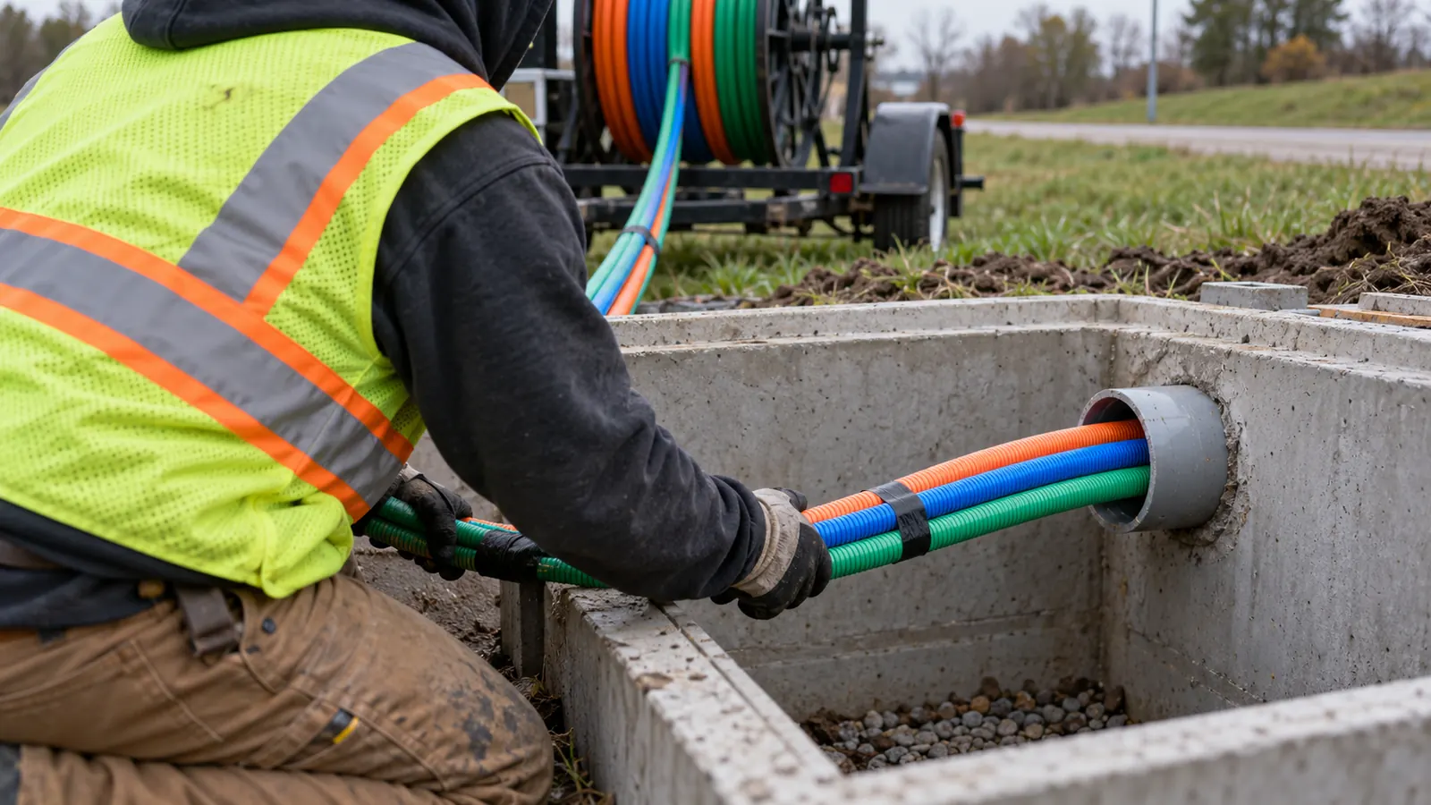
Innerduct is a smaller duct or fabric channel installed inside a larger conduit to separate fiber cables and preserve usable pathways. A conduit containing 3 innerducts can provide three distinct cable routes, but the allowable arrangement depends on actual diameters, conduit condition and the installation method.
An empty conduit can look generous at a handhole while a bend farther along leaves little room for the next cable. We start with the route between access points, because the opening visible to the installer cannot establish what will pass through the entire run. Diameter matters. So does the path.
The outer conduit carries the surrounding installation loads according to its design. A solid innerduct creates another wall around the cable; a fabric divider creates separate channels within the host conduit. We specify the outer conduit independently, then check whether the proposed subdivision leaves an installation that the owner can maintain.
Separate present occupancy from future access
A reserved channel needs a destination. When a design shows one occupied pathway and two spares, we want those spares identified at both ends and continued through the intervening structures, rather than ending wherever the first cable exits. Otherwise the drawing promises capacity that the next installation cannot use.
Color helps identify a duct. Labels establish its route. Our drawings should connect the channel designation to the correct conduit opening and show where that designation changes, especially when several banks enter the same vault. A consistent identifier lets the next installer check the intended path before disturbing an occupied one.
We also separate cable capacity from pathway capacity. More fibers within a selected cable do not necessarily require more innerducts, while two cables serving different maintenance needs may justify separate pathways even when their combined area is small. The owner's replacement strategy belongs in this decision before the duct schedule is issued.
Plan the complete cable path
A cable route includes the turns inside access structures. We check how a cable leaves its innerduct and reaches the intended rack or splice location without violating its installation bend radius, even where the buried conduit itself has a generous sweep. A cramped vault can defeat an otherwise workable duct selection.
The distinction between route design and product selection matters here. Our fiber network design work connects cable assignments to usable pathways, so the duct schedule supports the network instead of becoming a separate materials list. We carry that assignment into the detail at each access point.
How many innerducts fit inside a conduit?
Use actual dimensions first. The host conduit's inside diameter, or ID, is the available envelope; each solid innerduct's outside diameter, or OD, occupies part of it. Trade sizes identify products, but they do not supply all the dimensions needed to calculate the proposed arrangement.
A worked geometric example
Consider an illustrative circular host with a 4.00-inch clear ID and identical innerducts with a 1.25-inch actual OD. Three innerducts occupy 3 × (1.25 / 4.00)² × 100, or about 29.3% of the host's cross-sectional area. Four occupy about 39.1%. These are calculated examples, not a recommendation for a nominal product.
Four equal circles also need room to pack. In a square arrangement, their enclosing circle has a diameter of approximately 2.414 times one innerduct's OD, giving about 3.02 inches in this example. That fits inside the assumed 4.00-inch circle geometrically. Installation still needs a separate check.
Now consider the same four innerducts with an actual OD of 1.75 inches. Their enclosing circle would be about 4.22 inches across, exceeding the same host bore before any allowance for pulling clearance. The trade description alone cannot reveal this conflict. We use the submitted dimensions and verify the minimum clear opening along the route.
Area fill does not establish pullability
A flattened section can govern an entire run. Coupling restrictions also matter. We review the field condition before accepting an existing conduit as available, and our conduit fill ratio design guide explains why the area calculation must stay connected to the intended cable installation.
The Plastics Pipe Institute's undated Innerduct Frequently Asked Questions suggests 50% casing fill for short straight runs and 30% for longer complex runs, with 70% as its maximum recommended value. We treat that guidance as a screening reference, not a universal permission to fill every conduit to a fixed percentage. The product instructions and route-specific installation review must support the chosen arrangement.
For the cable inside a solid innerduct, calculate area fill again using the cable OD and the innerduct ID. A 0.50-inch cable in a 1.00-inch bore has a 50% diameter ratio but only 25% area fill. State which ratio you mean. Confusing the two can make the same design appear to have twice its actual area occupancy.
| Product type | Pathway form | Selection question | Check before specifying |
|---|---|---|---|
| Smooth-wall HDPE | Continuous solid tube | Is a separate bore needed? | Actual ID and installation limits |
| Internally ribbed HDPE | Solid tube with internal ribs | Does the profile suit cable placement? | Usable bore and cable compatibility |
| Corrugated HDPE | Tube with a corrugated profile | Does flexibility suit the route? | Application rating and bend limits |
| Fabric mesh innerduct | Flexible channels within host conduit | Can subdivision preserve usable space? | Channel capacity and installation procedure |
HDPE vs fabric mesh innerduct: choose the pathway
We compare these products against the intended cable placement and replacement method. The table separates four product forms; it does not rank every product within them. A material name leaves important questions unanswered when the cable must pass through several bends or enter a structure at an awkward angle.
Smooth-wall HDPE
A smooth-wall tube provides a defined bore that can be dimensioned on the duct schedule. We favor this arrangement when the owner needs a distinct, traceable pathway and the host conduit has adequate room for the tube wall. The spare remains a separate tube even before a cable occupies it.
Wall thickness consumes space. That is a real limitation of our preference for solid ducts where future cable access matters: reserving separate bores can reduce the total cable area available inside the host. We accept that trade-off only when the maintenance benefit justifies the geometry, rather than treating more plastic as an automatic improvement.
Internally ribbed HDPE
Internal ribs change the cable-contact surface within a solid tube. We ask for the usable bore dimension instead of calculating cable clearance from an assumed smooth interior. The profile at the rib tips can matter when a cable or pulling assembly approaches the available opening.
Ribs alone do not establish a longer achievable pull. The PPI innerduct FAQ cautions that reel memory and spiraling can dominate pulling friction, so we require installation information for the selected cable and duct combination. Our specification should not turn a surface feature into an unsupported performance guarantee.
Corrugated HDPE
Corrugations give this product a visibly different profile from a tube with internal longitudinal ribs. Read the section drawing. We check whether the proposed product is intended for the outer-conduit environment and how its specified bend radius affects the route into the access structure.
The outside profile also affects occupied space. A calculation based on the valleys rather than the maximum OD would understate the envelope that must pass through the conduit, particularly at a restricted joint. We want the dimensional basis stated on the submittal so the field team can compare the delivered product with the approved design.
Flexibility does not establish an indoor fire rating. Outdoor corrugated HDPE and listed indoor corrugated raceways can look similar, but we select them by application and listing. A photograph or a color description cannot resolve that distinction for the person ordering material.
Fabric mesh innerduct
Fabric mesh products subdivide the host into flexible channels rather than adding several separate rigid circular envelopes. Channel capacity must come from the selected assembly's instructions and cable dimensions. We do not assign each empty fabric channel the same fixed ID used for a solid tube.
PPI's Comparison of HDPE Conduit and Fabric Divider Installed as Innerduct, TN-59, first issued in August 2019, distinguishes fabric separation from a solid duct's additional mechanical protection. It also identifies twisting as an installation concern. We use the fabric assembly's specified installation procedure and confirm channel continuity before accepting spare capacity.
For a constrained existing pathway, fabric deserves a specific evaluation. We compare the proposed cable assignments against the actual occupied conduit and the approved installation method, with particular attention to protecting cables already in service. An unverified spare channel should remain an unresolved design item rather than an available route on the owner's records.
Pull tape, pulling tension and cable installation
Pull tape provides a means to draw material through the pathway; its rating does not become the cable's permissible pulling load. We check the allowable load at the cable attachment and the limits of the pulling components. The lowest applicable limit governs the operation.
Write the pulling plan around the cable
A design package should identify the cable construction before it assigns a tension limit. We require the cable supplier's maximum installation tension and bend-radius requirements, then assess the pulling route with the proposed grip or pulling eye. A tension value copied from another cable can leave the installer with an unsafe target.
Consider a hypothetical cable limited to 300 pounds of pulling tension and a tape carrying a 1,250-pound breaking-strength label. The stronger tape does not authorize a pull above 300 pounds, and its breaking strength must not be mistaken for a working-load rating. Other components may require an even lower operating limit.
Bends concentrate contact forces. We therefore consider cable loading at a bend even when the pulling equipment reports a tension below the cable's maximum, because the local radius and contact condition can still be unacceptable. The route review should address the entrance guide and the buried sweeps together.
Keep the pull limit visible: Put the approved cable tension limit where the pulling operator can use it, and define the stop condition before the operation begins. A buried note in the material submittal is easy to miss during setup.
Pull tape belongs in the material specification. We identify its required working capacity and compatibility with the pathway, then confirm that the selected attachment method preserves the permitted load. Footage markings can help track a pull, but the installation record still needs the actual endpoints and the cable identification.
Factory-installed tape reduces uncertainty about whether a pull line was provided. Its ends still need protection. During closeout, we want each spare pathway's pull medium identified and secured so a subsequent installer can find it without opening occupied cable attachments or guessing which line reaches the intended structure.
Existing occupied conduit needs special attention. TN-59 warns that a pulling line can abrade an existing cable where they cross. We require an approved method for the occupied condition, rather than assuming that enough calculated open area makes it acceptable to winch another assembly through the same bore.
Air-assisted installation has its own requirements. A pressure-compatible solid duct system may support cable jetting when the cable and equipment are matched to it; an open fabric channel does not itself create a sealed air path. We confirm the proposed method before choosing couplings and termination details.
Access spacing belongs in the same review. Our splice-point placement guide covers decisions that influence where the cable must be handled, while conduit and duct bank design resolves the physical pathway. Neither drawing should assume the other has already settled the pulling arrangement.
Where plenum and riser innerduct belong inside buildings
The building entrance changes the specification. We identify the indoor route and its environmental classification before extending an outdoor material callout through the wall, because a product suitable inside buried conduit may lack the listing required for the space beyond it.
Plenum spaces and vertical risers
Listed plenum raceway belongs where the approved design requires a product evaluated for environmental-air spaces. A ceiling void may serve that function, but being above a ceiling alone does not establish its classification. We confirm the air-handling arrangement with the building design and the authority having jurisdiction.
Listed riser raceway serves permitted vertical applications between floors. Riser suitability alone does not establish plenum suitability. UL Standards & Engagement's Cable Routing Assemblies and Communications Raceways, UL 2024, fifth edition, published March 25, 2014 and revised November 17, 2021, distinguishes these applications; the exact product listing and locally adopted code govern the proposed installation.
The cable requires its own review. For example, OFNP and OFNR are optical-fiber cable designations, so specifying a cable marked OFNP does not by itself establish the listing of the surrounding raceway. We check both components against their intended location and document any required change at the transition.
Entrances, supports and penetrations
Show the transition on the drawing. We define where the outdoor pathway ends and where the approved indoor system begins, with a detail that accommodates the cable's bend radius. That location should be identifiable to the installer without requiring a field interpretation of a general note.
A fire-rated penetration needs a matching approved firestop system. We coordinate the opening and the cable or raceway configuration with that system, because substituting a different diameter or adding a spare channel can change what the penetration detail permits. A water seal and a firestop serve different functions.
Support requirements remain part of the installation. A flexible indoor raceway must follow its listing and installation instructions rather than hanging from whatever service happens to share the ceiling. We also identify access needed for future cable placement before a finished wall conceals the transition.
Choose innerduct for the next cable, too
For owners building a new route: reserve solid pathways where future replacement needs a distinct bore, and size the host around the selected products' actual dimensions. We recommend resolving spare destinations during design so the installed reserve reaches the locations where the network can expand.
For owners reusing occupied conduit: establish the existing condition before choosing a divider. Evaluate fabric where its channel arrangement fits the intended cables, but require a supported installation method that protects the live plant. We would not recommend accepting capacity solely from an area-fill calculation.
For building owners: specify the indoor pathway by space classification and listing, with the entrance transition shown explicitly. Keep the cable and raceway requirements separate in the material review. That makes a proposed substitution assessable before the wrong product reaches a concealed space.
Draftech International delivers turnkey telecom and power infrastructure with engineering 100% in-house and full turnkey construction delivered by Draftech-managed crews under Draftech's QA/QC. Active in 24 states. Available across all 50 U.S. states. Our partner-led delivery team connects pathway decisions to construction drawings and closeout records. Use our project contact page or info@draftech.com to discuss a route whose spare capacity or building transition remains unresolved.
For a qualifying route, Draftech's free design offer covers engineering the first 20,000 linear feet at no cost, from feasibility and field survey through permit approval. The owner reviews each request before Draftech commits the package, so the proposed route and its pathway requirements can be considered before the engineering scope is accepted.