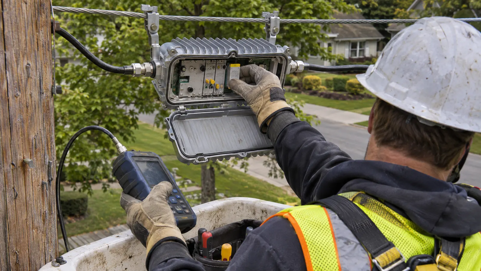
Where a line extender fits in the coax cascade
A line extender is the RF amplifier in the coax distribution legs after the node that restores signal ahead of the taps. CableLabs describes N+1 as a node followed by a single amplifier; the device belongs in that active coax path, where its gain compensates for the losses between signal sources and subscribers.
The name also appears in marketing and in CAD or GIS line tools. Consumer extenders use similar terminology. Here, the subject is the outside plant cable amplifier. Its location matters as much as its gain. A housing shown on an old drawing marks an existing asset, but retaining that location requires a branch calculation for the proposed network.
For our design review, the useful question is what reaches the amplifier input and what its output must support. That question follows the coax route. It cannot be answered from the straight-line distance between symbols, particularly where the distribution leg turns through side streets or passes several taps before reaching the next active.
Count the amplifiers on the actual signal path
CableLabs' P2P Coherent Optics Architecture Specification, issue P2PCO-SP-ARCH-I01-180629, issued June 29, 2018, uses N+0 for passive coax after the node and N+1 for a path with a single amplifier. The notation describes cascade depth. It does not count every housing spread across all the node's branches, and the node itself is the starting point rather than an added coax amplifier.
A downstream branch can therefore have a different active depth from a neighboring branch served by the same node. Trace each path separately. For us, an aggregate equipment count is useful for inventory, while the ordered path is what allows a designer to assign the loss between stages and judge the resulting cascade.
The distinction becomes practical when a contractor reads a proposed removal. An amplifier removed from one leg does not automatically change the active count on another leg, even if the equipment symbols sit close together on the sheet. The revised path must remain explicit. Our HFC node explanation of N+x and the power path covers the node-side context without making the distribution amplifier responsible for the optical link.
Keep through loss separate from tap loss
A tap has different losses for different paths. The loss along the continuing feeder enters the calculation toward the next amplifier, while the loss from the feeder to a subscriber port enters the calculation toward that subscriber. These are separate quantities. Applying the subscriber tap value to every through connection can distort the entire branch budget.
The downstream level at the amplifier output must support the remaining cable and the intended tap arrangement. An adequate input at the next active does not prove that every subscriber path between the actives is acceptable. For our spacing calculations, the intermediate taps remain part of the design rather than disappearing into a single total distance.
How line extender spacing and gain are calculated
The upper design frequency establishes an essential starting point for cable-loss calculations. CableLabs' Cable Broadband Technology Gigabit Evolution describes a DOCSIS 3.1 frequency span from 5 MHz to 1218 MHz. That published span supplies context for a proposed band plan; it does not establish the deployed upper edge of a particular operator's plant.
Cable attenuation rises with frequency, so a route calculated only at a lower reference frequency can understate the loss at the proposed upper edge. Use the operator's actual target. Our gain calculation needs attenuation data for the specified cable at that frequency, applied to the routed cable length and the design conditions the operator requires.
Calculate the interval before choosing the location
The basic downstream relationship is straightforward: the preceding output level minus the intervening path loss gives the next input level. Gain then relates that input to the intended output, subject to the amplifier's operating limits. Keep the reference conditions consistent. Comparing a per-channel level with a total composite level would produce a misleading result even if the arithmetic were correct.
The interval loss includes cable attenuation and the insertion loss of every passive device on that path. Both depend on the actual equipment. A branch with a short cable run can still consume substantial signal level in its passive network, while a longer, lightly loaded route can produce a different result. Distance alone leaves that difference unexplained.
Temperature assumptions also belong beside the cable data. Our preference is to make the applicable condition visible where the interval is calculated, because a value copied from an unrelated reference condition can move the apparent amplifier location. The calculation should let the reviewer identify which assumption controls the available spacing without reverse-engineering an unexplained total.
| Design input | What it determines | What the drawing must preserve |
|---|---|---|
| Upper design frequency | The cable and passive loss values used | The frequency basis for the branch |
| Routed coax length | Cable attenuation between active stages | The route associated with each interval |
| Tap through loss | Loss continuing toward the next active | The correct through-path components |
| Subscriber tap loss | Level available toward the drop | The tap assignment at that location |
| Input and output objectives | Required gain and available headroom | The reference conditions for each level |
Once the interval is understood, placement becomes an engineering choice tied to the route. A suitable amplifier must provide the required gain without forcing an unacceptable input or output elsewhere in the branch. Moving the active changes the losses on both sides. Our branch calculations for an HFC coax upgrade explain the wider upgrade review that sits behind this placement decision.
Separate signal level from signal quality
More gain raises what enters the amplifier, including unwanted energy already present with the wanted signal. The amplifier also contributes noise and can introduce distortion. Those effects accumulate through the cascade. Recovering a downstream level therefore does not restore the quality that an upstream impairment has already removed, and a stronger output alone cannot establish an acceptable design.
A longer cascade needs a whole-path review against the operator's quality criteria. Its stages interact. An output objective that looks convenient at an individual housing can consume distortion margin when the complete loading and downstream chain are considered, especially if the proposal keeps every existing location and asks gain to absorb all the changes.
A limitation of our preferred branch-by-branch calculation is that it depends on accurate cable and passive records. Missing data can conceal the controlling loss. The design should identify an unresolved input explicitly rather than make a precise-looking gain choice from it; otherwise the drawing gives the contractor confidence that the supporting calculation has not earned.
Keep the reference frequency visible. Put the frequency beside a loss total whenever that total supports a placement decision. A bare dB value can be copied into a later revision after the band plan changes, leaving the arithmetic intact but the design basis wrong.
The HFC cascade review addresses the system-level consequence of accumulated impairments. At the branch level, our role is to keep amplifier spacing and gain tied to that larger design. Draftech's HFC cable network engineering covers RF cascade design with amplifier spacing and gain calculations. Power insertion point design addresses the connected power path.
Powering the amplifier over the coax
The RF path and the power path share coax, but their boundaries can differ. ANSI/SCTE 271 2021, Requirements for Power Sensing in Cable and Utility Networks, identifies 60/75/90 VAC quasi-square wave HFC networks. These are descriptions of plant-power systems, not a direction to apply any of those voltages to an unspecified amplifier.
A power insertion point introduces the supply onto the intended coax path. Power-passing components carry it toward the active equipment, while power-blocking boundaries separate portions of the network. Follow that path independently. Our power insertion point design must account for the equipment that remains connected after a branch change, including loads beyond the amplifier being moved.
Coax resistance and connected load affect the voltage available at a remote active. The equipment's accepted input range matters. A location can work in the RF calculation and still need a different powering arrangement, which is why the nearest supply symbol cannot substitute for tracing the actual electrical path through the proposed plant.
For a contractor, an amplifier deletion needs an equally clear disposition for the continuing coax. Removing an RF stage can leave downstream equipment dependent on the same power route. Our placement decision therefore stays connected to the power insertion drawing; the design must explain the intended continuity instead of relying on a crew to infer it from the old arrangement.
What a split change or fiber deep asks of the amplifier
A split change moves the boundary between upstream and downstream spectrum. CableLabs' Gigabit Evolution paper describes upstream upper band edges between 42 and 204 MHz. That range explains why an amplifier can remain in the right physical place yet become unsuitable for the intended signal paths. Band compatibility comes before a decision to retain the device.
Re-space when the interval no longer works
A proposal that also extends the downstream upper edge changes the loss calculation along the coax. Recalculate the interval. Higher-frequency attenuation can consume margin that existed under the old band plan, and the installed spacing may no longer support the intended input levels even where the replacement amplifier has the desired frequency capability.
Re-spacing is appropriate when changing the active's position produces an acceptable branch and remains consistent with the operator's cascade objective. It changes more than a symbol. The revised location shifts the upstream interval and the downstream interval in opposite directions, so our review must follow both before the drawing identifies the new position as resolved.
The subscriber paths between those positions deserve equal attention. A move that helps the next active can alter the level presented to intervening taps or require a different passive arrangement. Preserve the branch relationships. The design is ready for issue when the proposed location and the associated calculations describe the same network, including the connections that remain in place.
Replace when the required bands exceed the equipment
A housing's presence on the route says little about the frequency capability of its contents. Replacement is warranted when the required operating bands or performance envelope exceed what the retained equipment supports. Our decision starts with the operator's equipment information, not an assumption that similar-looking housings carry equivalent RF paths.
The upstream and downstream paths need to support the intended split together. Check both directions. An acceptable downstream upper edge cannot establish upstream suitability, and changing the return band alone does not prove that the whole branch supports a simultaneous downstream expansion. The approved frequency plan is the common reference for those separate questions.
Distinguish replacement from relocation. A replacement at the same position preserves the physical interval, but its suitability still depends on the new loss and gain calculation. State the intended position clearly so equipment substitution does not silently become a placement decision.
Retire when the new node can serve the passive branch
Moving fiber closer to subscribers can shorten the coax path enough to remove an RF stage. CableLabs' architecture specification describes fiber-deep nodes at N+1 or N+0. The distinction matters. Fiber deep can leave an amplifier in service; only the passive-coax case removes every downstream RF amplifier on the applicable path.
Retirement follows the new node's reach through the retained passive network. Proximity alone is insufficient. A node moved closer on the map still has to support the actual cable route and subscriber tap paths, and our review must account for the losses that remain after the amplifier disappears from the drawing.
The power arrangement can change at the same time. A retired amplifier removes its own load, but a replacement node or a different supply boundary can change what the continuing coax carries. Preserve the intended connections. The future drawing should identify the network that will exist after the migration, rather than combining proposed node placement with an unchanged legacy power path.
An operator should evaluate retained-amplifier and passive-coax alternatives against the same planned service area. Otherwise the apparent advantage may come from comparing different branch extents. Our preference is to establish the intended endpoints first, then compare how each design reaches them. That makes the decision reviewable by an engineer who did not prepare the original placement.
Choose the disposition before issuing the branch drawing
For an operator retaining an amplified branch, keep the existing location only when the proposed band plan and recalculated interval support it. A drawing revision should identify the basis for retention. Our recommendation is to resolve the controlling loss before selecting equipment, because a nominal gain value can conceal an input-level problem rather than solve it.
For a split upgrade, separate frequency compatibility from spacing. Replace equipment that cannot support the intended bands, then determine whether the established location still works. The operator's chosen spectrum governs the decision; the 1218 MHz span described by CableLabs is a reference for DOCSIS 3.1 capability, not permission to assume every existing branch already reaches it.
For a fiber-deep design, retire the active only after the new node's passive reach is established. Keep any remaining amplifier explicit in the cascade notation. A contractor should receive an unambiguous disposition for each affected housing, with the new connection shown where equipment is removed and the intended power continuity preserved through the change.
Before requesting our engineering support, assemble the current branch information and identify the proposed band plan. The most useful starting material shows the actual coax route and the equipment on it. Missing component data should remain visible as an open input, so a design discussion can focus on the decision that data prevents rather than debate an unsupported output level.
Draftech International delivers turnkey telecom and power infrastructure, with engineering performed 100% in-house. The partners responsible for our delivery provide the company context behind that accountability. Full turnkey construction is delivered by Draftech-managed subcontract crews under Draftech's QA/QC; the engineering conclusions in the branch drawing establish the intended work for those crews.
A branch that cannot reconcile its proposed spacing with its power path needs coordinated RF cascade design and power insertion point design. Send the proposed change through our HFC design inquiry page or email info@draftech.com with the affected route identified. That gives us a specific starting point for amplifier spacing and gain calculations rather than a request to approve an isolated equipment label.
For a qualifying route, Draftech engineers the first 20,000 linear feet at no cost, from feasibility and field survey through permit approval. Our free design request lets you present that route for consideration. The owner reviews each request before Draftech commits the package.