IN THIS ARTICLE
What is an HFC node?
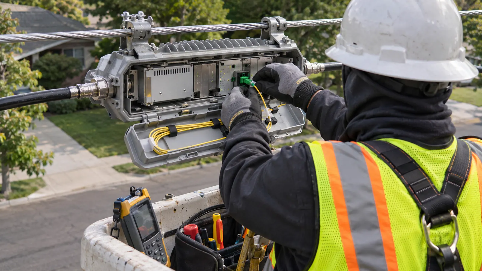
An hfc node, also called an optical or fiber node, is the enclosure where hub fiber meets coax: it converts downstream light into RF for the coax legs and upstream RF into light. Its 2 signal directions connect the optical transport network with the coaxial distribution plant serving subscriber premises.
The enclosure marks a change in transmission medium. It also anchors the outside-plant design. For cable operators and ISPs, its location affects which addresses share the downstream plant and how that plant returns traffic toward the hub. For designers and builders, the same location sets the starting point for coax routing and the destination of the incoming fiber.
We start with that physical relationship because a node symbol can hide a difficult route. A proposed site may look central to the intended serving area while sitting across a road from the usable coax, or beyond the reach of the existing power arrangement. Moving the symbol changes the work. Our design has to follow the actual cable path rather than the shortest line between addresses.
The downstream and return paths
In a conventional analog optical node, the downstream receiver recovers RF carried over fiber and feeds the coax distribution outputs. The return path collects upstream RF from that distribution plant and sends it toward the hub through an optical transmitter. Direction matters. A drawing that records only the downstream legs leaves the return-path connectivity unresolved, even when the enclosure and its outgoing cables appear correctly located.
We distinguish the housing from the network functions inside it. An optical endpoint using digital transport can occupy a similar outside-plant position while handling the signal differently from an analog node. The operator's architecture therefore belongs in the design basis before our team assigns fiber routes or treats an existing enclosure as suitable for a proposed change.
The wider hybrid fiber-coax engineering process connects those node decisions to the retained distribution plant. Here, we keep the focus on what the enclosure needs from its site and what its location does to the surrounding network. Electronics selection and operation remain with the operator's specialists.
What an HFC node holds
The functional starting point is SCTE 38-5 2017, reaffirmed in 2022, Hybrid Fiber/Coax Outside Plant Status Monitoring SCTE-HMS-FIBERNODE-MIB Management Information Base (MIB) Definition. SCTE's catalog describes a management model covering optical receivers, optical transmitters, ports and power supplies. That reference helps identify the functional parts of a conventional node; it does not prescribe a universal enclosure layout or a complete installation design.
Optical receiver and return transmitter
The optical receiver belongs to the downstream signal path, while the return transmitter handles the upstream optical path in the conventional arrangement described above. Their external fiber connections must agree with the operator's transport plan. We carry the required fiber assignments into the route and splice documentation, including the relationship between the node identifier and the termination at the other end.
A nearby fiber cable does not establish usable connectivity. Its route may be suitable while its assigned fibers are already occupied, or its accessible splice location may require a different approach to the enclosure. We resolve those route questions against the owner's records and field observations. The operator supplies the optical interface requirements that govern the connection.
RF ports and internal power supply
RF ports connect the node to its coax legs, but the number of visible connections alone does not establish how traffic is grouped internally. The operator's port arrangement determines which distribution branches share a signal path. We need those assignments first. A cable drawn against the wrong port on the RF design can misrepresent the intended serving boundary.
The node also needs operating power. Its internal supply serves the electronics, while the outside-plant power design determines how energy reaches the enclosure. Those are separate design questions. A nearby supply cabinet does not prove that the intended path can carry the proposed load under the operator's required conditions, especially when retained amplifiers also depend on that path.
Keep identifiers connected: Use the same node ID on the fiber splice detail and RF drawing. Port labels should then identify the outgoing coax legs without forcing the reader to infer their destinations from physical proximity.
Strand, pedestal or wall: what the site must support
Mounting follows the available plant. The operator must also accept the enclosure arrangement. The design should establish how the housing is supported and how a technician can reach it after construction. We review the cable approach at the same time. A mounting location that works for the enclosure can still fail when the required cable bends or service access are drawn at usable scale.
| Design interface | Input to confirm | Where it appears |
|---|---|---|
| Fiber approach | Available assigned fibers and an accessible splice location | Route drawing and node termination detail |
| Coax legs | Port assignments and the retained branch connections | RF design with existing and proposed paths distinguished |
| Mounting | Accepted support arrangement and maintenance access | Site detail tied to the surveyed location |
| Powering | Supply path and operator-specified connected loads | Power insertion design coordinated with retained plant |
Strand mounting
A strand-mounted node sits in the aerial plant, supported by the approved mounting assembly. The supporting span matters. We check the proposed position against the attachment arrangement and the cable route, with pole-owner requirements addressed through the applicable engineering and permission process. The enclosure's loading and its placement belong in that review rather than being treated as incidental hardware added after the route is approved.
Our field record should show the approach from each direction and the working conditions around the site. A technician may need to reach the enclosure from a bucket while avoiding conflicts with other attachments, so an apparently open span cannot be accepted from a map alone. The issued detail should leave enough information for the responsible installer to identify the approved location.
Pedestal mounting
A pedestal arrangement places the node at ground level within an appropriate protective housing. Here, the design turns toward the occupied footprint and underground cable entries. We need to understand who controls the land and whether the enclosure remains accessible after nearby landscaping or other site work. Access must survive the finished condition.
The ground-level position also changes the exposure review. Drainage and the operator's environmental requirements affect which enclosure arrangement is acceptable, while the underground pathway must allow the specified cable to enter without an improvised bend at the base. Our route package records those physical interfaces. It does not assume that an available patch of ground is an approved node site.
Wall mounting
A wall-mounted arrangement depends on an approved support surface and the owner's permission to use it. The detail must account for the enclosure's attachment and cable entry requirements, with a practical maintenance position in front of the equipment. We avoid treating a wall as empty drawing space. Existing building uses can restrict access even when the physical support appears adequate.
The mounting choice should remain visible in the construction package. A strand detail cannot quietly become a pedestal detail when a route changes, because that substitution can alter property rights and the cable approach. Revisit the site decision when the support changes. The operator's accepted equipment requirements remain the basis for the final mounting arrangement.
What sets the serving area and why placement matters
A serving boundary starts with addresses, then follows the distribution network that can reach them. Homes passed describe the potential premises along that plant; they do not tell us how many subscribers are active or how much traffic a service group carries. We ask for those distinctions explicitly. A planning count becomes useful only when it is connected to the intended physical branches.
Coax legs and the N+x cascade
The coax legs establish the paths leaving the enclosure, and each path has its own losses and downstream devices. In N+x notation, N represents the node and x describes the RF amplifier cascade after it; N+0 means no downstream RF amplifiers. Passive coax components still remain. The absence of amplifiers therefore does not remove the need to evaluate the distribution path.
We trace the intended cascade along each branch rather than assigning an area-wide label and assuming every address fits it. Cable length and passive-device losses affect the RF design, while branching can leave different paths with different constraints. An address near the node on a street map may still be reached by a longer cable route around the block.
Our preferred starting point is the retained plant map, checked against field conditions before the new boundary is fixed. Its limitation is that incomplete records can conceal a branch connection that changes the proposed serving area. We leave that connection unresolved until it is confirmed. Drawing confidence should follow the evidence available for that particular path.
Powering can move the node
The power path deserves its own trace. Power insertion location, cable resistance, connected load and power-passing arrangements affect whether the proposed node position can use the intended supply. We coordinate the calculation inputs with the operator's equipment requirements. A branch that carries RF in the intended direction may still require a different power arrangement because of how its components pass or block power.
Moving the enclosure toward a difficult coax leg can shorten that branch while extending the fiber approach or changing the supply path. That is why we compare candidate locations against the whole physical design before issuing drawings. The closest pole is only a candidate. The accepted site has to support the intended connections and remain accessible for operation.
Where those interfaces need to be coordinated in one package, our HFC cable network design scope covers node-site fiber routes, power insertion, RF cascades and construction packages. We establish the physical relationships around the operator's selected equipment. Draftech does not provide node electronics, node configuration, alignment, testing or node installation under this scope.
Trace the supply boundary: When a proposed change moves coax legs between nodes, check which retained devices still depend on the existing power path. Keep that dependency visible even when the RF serving boundary moves elsewhere.
How node splits and other upgrades relate to the enclosure
Upgrade terms describe different changes. Before combining them in a project name, we ask which physical boundary changes and which network function changes. The answers guide different parts of the drawing set. A route designer needs a definite destination for fiber even when the operator is still deciding how channels will be assigned to the resulting plant.
Node splits and DOCSIS service groups
A node split divides an existing serving arrangement into smaller segments, and our node segmentation engineering discussion follows the associated boundary changes. Some projects require another physical site; others depend on how the operator segments available paths. We need the proposed result expressed as connections, not just as a request to split the node.
CableLabs' DOCSIS 3.1 MAC and Upper Layer Protocols Interface Specification, revision CM-SP-MULPIv3.1-I25-230419, published April 19, 2023, or MULPI, defines service groups through channel reachability, including the downstream channels from a MAC domain that reach a fiber node. This separates a logical service grouping from the enclosure itself. The operator supplies the channel-to-plant relationship. We cannot infer it from the number of housings on a map.
A physical drawing can show where a coax branch goes without proving how its traffic shares capacity with another branch. Keep both records connected. The operator's service-group plan supplies the logical relationship, and our plant documentation supplies the physical route against which that relationship can be checked. This distinction prevents an added enclosure from being treated as proof of a completed capacity change.
Fiber deep, spectrum splits and Remote PHY
Fiber deep design extends the optical network toward subscribers and often reduces the amplifier cascade toward N+0, while retaining coax beyond the optical endpoint. That changes the distribution distances the designer must evaluate. We use the intended cascade as an input to node placement rather than assume that moving fiber closer automatically makes every retained coax path suitable.
A spectrum split changes the allocation between upstream and downstream RF bands and requires compatibility across the affected signal path. It is a separate decision. We need the operator's chosen frequency plan before evaluating the retained RF cascade, because the drawing must represent the plant intended to carry that plan rather than an unspecified future upgrade.
Remote PHY moves physical-layer processing toward the node and uses digital transport between the remote device and the core, as described in CableLabs' Remote PHY Specification, revision CM-SP-R-PHY-I21-251211, published December 11, 2025. It does not, by itself, set the coax cascade length. The outside-plant team needs the resulting fiber and site requirements, while the operator retains responsibility for the remote device's electronics and operation.
The construction sheets also need to distinguish existing connections from proposed ones. We use the owner-approved drawing conventions to show which coax remains and where a new fiber approach meets the node site. Identify the affected connection directly. A builder comparing the plan with the field should not have to reconstruct the intended change from an old overview.
Closeout should preserve that same relationship. If an approved field change shifts the approach to the enclosure, our as-built documentation needs the revised route and its connection to the node identifier, rather than a moved symbol with unchanged cable records. The operator can then compare the delivered physical plant with its own service-group records without treating the two records as interchangeable.
Release a buildable node-site package
For cable operators and ISPs: Set the intended serving boundary and give the designer the corresponding port and transport requirements before accepting a node location. Separate homes passed from active demand. Our route work can then support the physical change you intend, while your network team confirms that the channel grouping provides the intended service arrangement.
For HFC designers: Reconcile the fiber approach with each outgoing coax leg before fixing the site. Carry the power-path dependencies into the same review, especially where an existing supply continues feeding equipment beyond a changed RF boundary. We recommend resolving a disputed connection before drawing its proposed replacement. An assumption in the existing topology can propagate into otherwise precise construction sheets.
For builders: Use the issued node location and mounting detail to identify the surrounding pathway work, and raise a conflict before substituting another support or enclosure position. A relocation can change more than the immediate cable length. The designer should determine its effect on the retained distribution plant before the revised route becomes the field record.
Our partner and delivery information identifies the team behind that coordination: Draftech International delivers turnkey telecom and power infrastructure, with engineering performed 100% in-house. Full turnkey construction is delivered by Draftech-managed subcontract crews under Draftech's QA/QC. For this node-design scope, the operator's specialists retain the node-equipment work described above.
When the fiber approach conflicts with the coax or power path, bring those drawings to our team through the project contact email. We can define the node-site route and construction-package scope around those specific conflicts, with the operator's equipment interfaces established before the site is treated as ready for construction.
For a qualifying route, Draftech engineers the first 20,000 linear feet at no cost, from feasibility and field survey through permit approval, under the first-route engineering offer. The owner reviews each request before Draftech commits the package. A node-area project should describe the route needing that engineering so the request can be evaluated against the offer.