- Hybrid Fiber Coax Engineering Begins with a Measured Plant Baseline
- Release the HFC Upgrade with a Five-Gate Engineering Matrix
- Keep DOCSIS Migration Honest about RF and Return-Path Constraints
- Control Field Migration, Leakage and HFC Acceptance
- Choose the Hybrid Fiber Coax Engineering Path by Plant Condition
An HFC upgrade is easy to oversell because the architecture has several levers that sound interchangeable; a node split is not the same as adding spectrum. Distributed access does not repair damaged coax. Fiber deep does not turn the remaining plant into FTTH. The design has to say which bottleneck each change addresses.
This guide follows HFC engineering from plant evidence through migration and acceptance; Draftech performs engineering in-house. Qualified subcontract crews complete physical construction under our management and oversight when construction is included. We do not claim that one architecture fits every MSO or that an upgrade can preserve every legacy device.
Hybrid Fiber Coax Engineering Begins with a Measured Plant Baseline
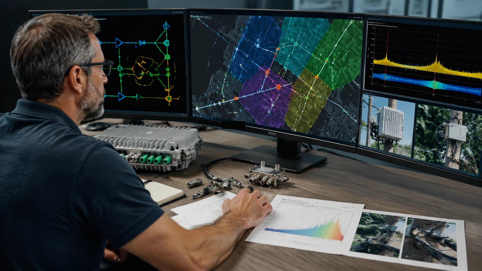
Hybrid fiber coax engineering controls 2 linked domains: optical transport to the node and RF distribution beyond it; a credible baseline identifies node boundaries, active cascades and power supplies before an upgrade path is selected. A strand map alone cannot prove RF condition, while a sweep record alone cannot establish route ownership or constructibility.
We start by establishing the current service-group boundary and tracing its physical plant; that means resolving which coax legs belong to the node, where active devices sit and how power reaches them. Database names are not enough. If the map says one node and telemetry says another, the conflict becomes a field task.
The baseline separates installed identity from assumed capability; housing style does not prove the module inside. A legacy tap faceplate does not reveal every prior change. We record make plus model when accessible and state where identity is inferred. Substitution history matters because an apparently uniform cascade can contain incompatible generations.
Operational evidence belongs beside geometry; we review available sweep history, leakage observations and trouble patterns without presenting them as a controlled acceptance test. Telemetry can point to a weak leg. It cannot replace field verification of the specific devices affected by the proposed architecture. Keep the boundary clear.
Map the Node, Active Cascade and Powering as One System
Node segmentation changes service-group geometry; it also changes fiber demand and powering interfaces. The proposed node needs a lawful location plus physical access. Each new optical path needs capacity at the hub or headend. The design should never treat a node icon as proof that rack space or transport ports exist.
Active cascade review follows the RF path from the node to the last powered device; we identify amplifier role and spacing plus the passive network around it. The objective is not to preserve every active. It is to understand what a spectrum or split change asks the installed cascade to do.
Power supplies create another dependency; new nodes or actives alter loading and standby expectations. Engineering documents the power topology and assigns a capacity review to the responsible discipline. We do not infer reserve from nameplate alone. Battery condition and local practice are operational inputs, not decorative notes.
Release the HFC Upgrade with a Five-Gate Engineering Matrix
A gate matrix forces the program to choose a real migration state; the same neighborhood should not receive node segmentation drawings based on one architecture and amplifier bills based on another. We hold detail production until the hub, node and coax assumptions agree. Rework otherwise spreads quietly.
The 5 rows below preview the decisions that control low-level design; they do not promise throughput. Capacity depends on the complete platform configuration plus operating policy. The matrix exists to show what evidence must be accepted and what condition stops release before material is ordered.
| Engineering gate | Evidence required | Release decision | Stop condition |
|---|---|---|---|
| Service group | Node boundary; homes passed basis; utilization source | Split or retain current boundary | Serving area cannot be reconciled |
| Optical transport | Fiber path; hub interface; port and rack review | Node transport can be detailed | Required path or interface is absent |
| RF cascade | Installed actives; passives; cable lengths; field basis | Selected spectrum plan can be modeled | Critical device identity is unknown |
| Powering | Supply topology; load review; standby criteria | Power design can support the change | Capacity or ownership remains unresolved |
| Migration | Cut plan; compatibility matrix; test and rollback plan | Construction package may release | Legacy service impact has no disposition |
Decide Whether the Constraint Is Service-Group Size or RF Spectrum
Node segmentation reduces the population sharing a service group when the serving map and provisioning change together; it does not expand the frequency range of the coax plant. Spectrum work changes the usable RF plan and can require new active plus passive devices. These are different interventions. Name the constraint first.
A fiber-deep design can shorten active cascades by moving optical conversion closer to subscribers; that can simplify RF paths, but it adds node sites and optical routes. It can also add powering work. The correct comparison includes hub resources plus field access. Counting only removed amplifiers makes fiber deep look easier than it is.
Passive compatibility needs device-level review; taps and splitters influence the forward and return paths even though they require no power. A program that replaces amplifiers but ignores old passives can preserve an unintended frequency constraint. We identify the affected passive population from records and field evidence, then define replacement criteria for the selected architecture.
Our middle-mile route planning guide covers transport reach outside the access plant; the last-mile fiber design guide explains full fiber distribution. The broader OSP engineering service stack for ISPs provides delivery context. HFC migration needs both views because a coax service area can move deeper into fiber without becoming a passive optical network.
Architecture gate: write one sentence naming the bottleneck before choosing node segmentation, spectrum expansion or fiber deep. If the sentence is vague, the design basis is not ready.
Keep DOCSIS Migration Honest about RF and Return-Path Constraints
DOCSIS is a system architecture, not a sticker on one node; CableLabs publishes the controlled specification family through its DOCSIS specification catalog. We reference the current platform documents selected by the operator without reproducing licensed specification text. Device support and software state must be verified for the actual vendor stack.
DOCSIS 4.0 planning can involve Extended Spectrum DOCSIS or Full Duplex DOCSIS; those are 2 distinct paths, not casual synonyms. The operator's access platform and installed plant determine the viable migration. We will not draw a generic DOCSIS 4.0 cloud and call the access network engineered.
The return path deserves its own evidence; ingress can enter through damaged cable, loose connectors or subscriber wiring. A higher split changes the band plan but does not remove those entry points. We review plant condition and device compatibility before finalizing the return architecture. Clean symbols do not clean RF.
Drop plant sits outside many upgrade drawings and inside the customer's actual signal path; the operator needs a policy for damaged drops plus incompatible premises devices. We show the network boundary and flag customer-side dependencies. Rebuilding the distribution cascade while leaving known ingress sources untouched can make commissioning look successful until traffic and seasonal faults return.
Use Distributed Access Only after the Hub and Field Interfaces Agree
Distributed access moves selected functions from a centralized facility toward the node; that can change the transport interface and hub equipment footprint. It also changes timing plus management dependencies. The design must identify which functions move and which stay. Saying DAA without naming the architecture leaves the most consequential boundary unresolved.
We inventory headend resources before issuing node packages; rack position and fiber termination need assigned ownership. So do switch ports plus timing sources. The outside plant team cannot solve a missing hub interface by adding another note to the node detail. The dependencies need one release date.
Provisioning is part of cutover readiness; a physical node can be installed correctly and remain unusable because the logical service-group definition is not prepared. We require the operator to assign configuration ownership and a verification step. Engineering records the dependency without assuming access to systems that remain under the operator's security controls.
One limitation of our preferred staged migration is temporary operational complexity; mixed service areas can require parallel spares and different troubleshooting procedures. We criticize plans that keep a transition state indefinitely. Every stage needs an entry condition and a defined exit, even when budget approval occurs in separate years.
Control Field Migration, Leakage and HFC Acceptance
A migration package names the current device and replacement identity at each location; it also states cable handling plus connector requirements from the selected manufacturers. The cut plan identifies affected service areas and rollback authority. Crews should not discover the compatibility matrix while the node is offline.
Construction sequencing protects usable plant while the migration is incomplete; fiber placement and hub preparation should clear before a cut window is booked. Power changes need their own release. We avoid sequencing every crew from one optimistic completion date. Each predecessor provides evidence that the next task can start without improvising a temporary architecture.
Signal leakage is an operating and compliance concern, not just a commissioning nuisance; the FCC's cable signal leakage guidance provides federal context for cable systems. The operator remains responsible for current requirements and its monitoring program. An engineering package does not certify systemwide compliance from one field reading.
Excavation for node pads or new conduit requires utility controls; OSHA 29 CFR 1926.651(b) covers locating expected underground installations and safe exact-location work as excavation approaches. State rules can add obligations. The subcontract employer retains its safety duties; a design note does not transfer them to engineering.
Draftech's HFC cable network engineering service performs the design work in-house; qualified subcontract crews execute replacements and new placement under our construction management when included. We also use qualified specialty partners for field disciplines that the migration requires. We do not claim self-performed cable construction.
Cutover rule: no service area releases until the replacement map, rollback owner and acceptance test set reference the same node boundary.
Close Each Service Area with RF, Optical and Asset Records
Acceptance is layered; optical transport is tested to the operator's criteria. The RF path is aligned and evaluated under the approved procedure. Asset records are updated to the installed identity. Passing one layer does not accept the others. A node online message is not a complete closeout package.
The redline process captures device substitutions and cable-route changes; it also records power-supply modifications. We tie exceptions to the service-group key so operations can find them after the construction ticket closes. Field notes in a contractor inbox are not durable plant records. Move them into the controlled system.
Configuration records need the same service-group identity as the map; a device serial in inventory is useful, but it does not show which architecture state operations should expect. We close the record with installed hardware identity and approved logical assignment. That pairing reduces the chance that later troubleshooting follows a superseded node boundary.
Migration limitations stay candid; old drop networks can continue to inject noise after an active upgrade. A shorter cascade can still suffer damaged coax. DAA can reduce analog optical links without resolving every outside plant defect. No architecture removes the need for maintenance access and disciplined records.
Choose the Hybrid Fiber Coax Engineering Path by Plant Condition
Match the Migration Scope to the Operator's Real Constraint
Stable spectrum with overloaded service groups: prioritize node segmentation after reconciling serving boundaries. Confirm hub ports and new fiber paths before field release. Do not replace every passive merely to make the project look complete. Change the components required by the selected architecture and condition evidence.
Aging cascade with repeated RF defects: evaluate fiber deep against targeted rehabilitation. Preserve coax only where inspection and testing support it. This is not a sentimental decision. If the remaining cascade demands recurring interventions that the operator cannot sustain, move the optical boundary and retire the weak section deliberately.
Operator preparing a DOCSIS 4.0 migration: select the platform path before mass design. Require a device compatibility matrix and staged cut plan. Our engineering delivery model fits programs that need one controlled architecture carried from hub interfaces through managed construction without blurring employer safety roles.
Unknown node boundaries create bad splits. Unverified devices create material surprises. Weak rollback plans extend outages. We remove those avoidable gaps by linking field identity to the migration package and acceptance record. If a program is choosing between segmentation and fiber deep, email info@draftech.com with the current node map plus platform constraint.
The recommendation is plain. Measure the installed plant. Name the actual bottleneck. Select one migration state. Release work by service group and close every layer with evidence. HFC remains an engineered system with real upgrade paths, but a standards label cannot compensate for unknown coax or an unresolved power plan.
Talk to Draftech about an HFC migration basis. Bring the node map and device inventory so we can separate architecture decisions from field verification gaps.