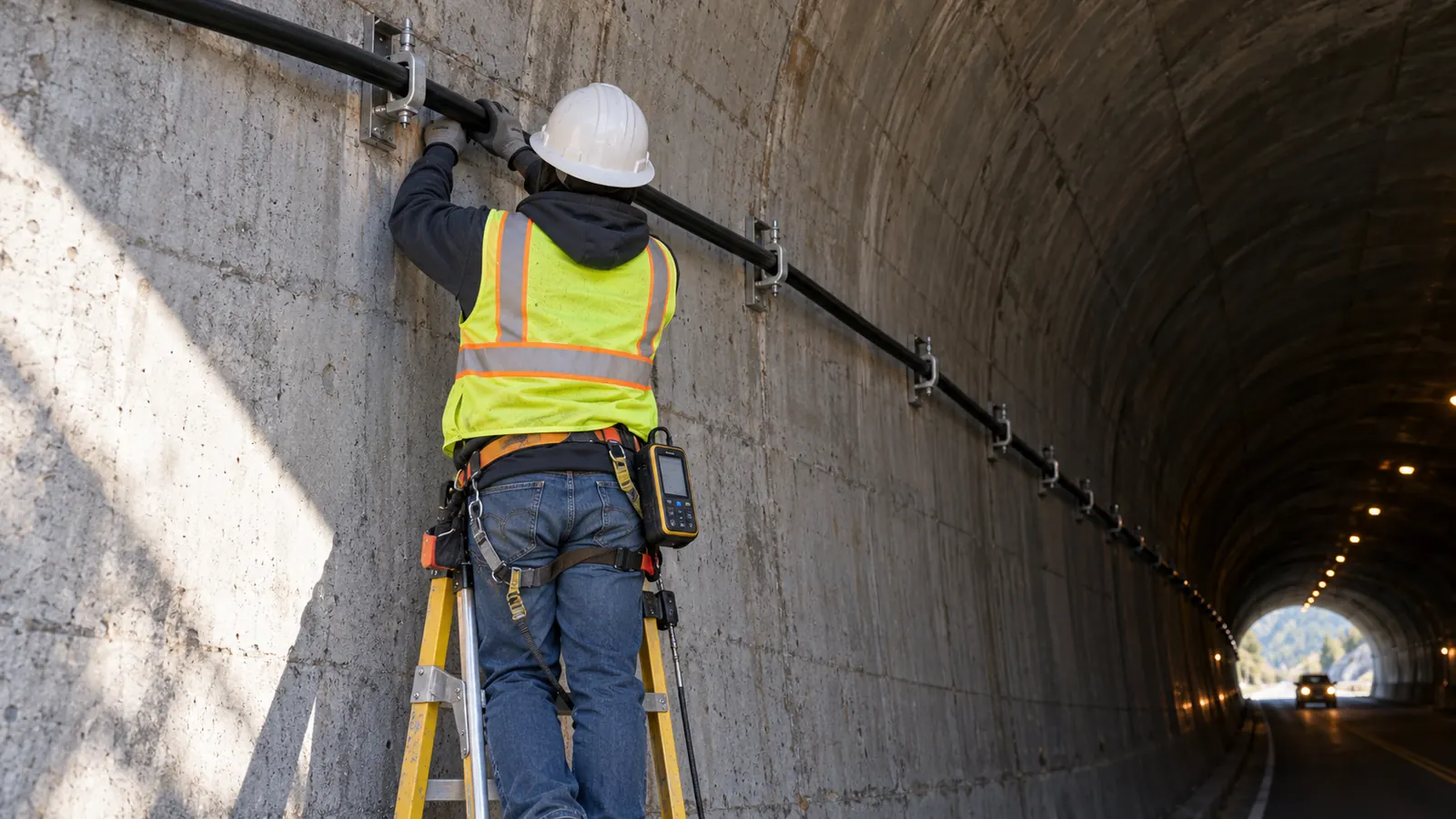
What is leaky coax, and where does it fit?
A leaky coax cable is coaxial cable with slots in its outer conductor that let it radiate and receive radio signals along its length. Also called radiating cable or leaky feeder, it serves long or shielded spaces. Its design depends on 2 distinct loss characteristics: longitudinal attenuation and coupling loss.
Ordinary cable-TV coax confines the signal for delivery between connected devices. With radiating cable, the cable itself becomes the antenna, intentionally coupling energy into the space beside its route. For a building owner looking at a long concrete corridor, the design question becomes where a continuous radiating path can serve the occupied space and how that route compares with the locations available for isolated antennas.
We start with the people who need coverage and the rooms they use. Walls can make a convincing line down the center of a floor plan misleading: an enclosed stair or the far side of a garage may still fall outside its reach. Before choosing cable, we establish the required radio bands and compare the proposed pathway with the actual coverage boundary, including the spaces separated from it by those walls.
Coverage follows the cable route
Radiating cable suits spaces whose useful coverage area stays close to a continuous route. In an open room, however, discrete antennas can be placed to suit the room's shape without following a cable run. We compare both layouts against the same service objective because neither wins everywhere. That comparison can rule out an otherwise convenient pathway when it leaves occupied spaces without the coverage they need.
For a narrow passage, our first layout compares radiating cable with a discrete-antenna alternative on the same plan. A limitation of radiating cable is that architectural changes can interrupt its continuous route, and moving the cable can change the RF result. If a cabinet is added beneath the run or a metal ceiling goes in, we revisit the prediction with those obstructions included, even if nobody has touched the cable.
Separate the distribution medium from the system
A cellular DAS architecture establishes the signal source and distribution arrangement. Radiating cable can serve as a radiating element within it, with active DAS components transporting signals over fiber to a remote unit that feeds a local cable section. That section still needs a radio source because passive cable cannot create service, secure carrier participation or add radio capacity to the system by itself.
Public safety DAS serves emergency responder coverage under the applicable authority's requirements, which need a separate design basis from ordinary cellular service. A BDA system uses a bidirectional amplifier, and its gain and isolation must suit the connected distribution network. Passive intermodulation can introduce unwanted signals at nonlinear passive junctions, so we treat connector selection and nearby metal interfaces as RF design concerns.
Where leaky coax beats discrete antennas
Long, constrained spaces are good candidates for a distributed radiating path. The bends and barriers along that path often matter more to us than its overall length. We look for a route that stays near users without creating inaccessible sections or crossing into spaces the cable cannot serve effectively. Comparing only the longest clear passage would leave the building's difficult areas out of the decision.
Corridors and shafts
A corridor is a useful candidate when doors and partitions limit the reach of antennas mounted farther away. Running the radiator beside the circulation path can reduce dependence on those distant ceiling locations, but we review the adjoining rooms separately. Behind a closed fire door, the room needs its own coverage prediction, particularly if its occupancy or service requirement differs from the corridor.
For a shaft, we first ask where the radio will be used: in the shaft itself, at a landing or inside an elevator car. Those are different receive locations, and the vertical cable layout has to account for the ones the owner needs. Moving equipment and access restrictions can dominate the layout. If the model represents only the shaft volume, it leaves the car enclosure and landing doors unresolved even though they affect the spaces users occupy.
Garages and tunnels
Garage ramps can favor a cable route that follows the vehicle path through successive levels. We assess discrete antennas for the wide parking bays as well, especially where columns and parked vehicles block users from the cable route. While we check those rows of vehicles separately from the ramp, the ceiling pathway also needs review to ensure that either arrangement retains the required vehicle clearance.
Tunnels are a familiar application because the required service area extends along a confined passage. That geometry explains the technology's fit, but tunnel communications also involve infrastructure-specific safety and operating requirements. This discussion explains the application; Draftech offers no tunnel delivery service within the building design scope described here. For buildings, the useful lesson is to model the actual passage instead of borrowing a generic tunnel coverage distance.
| Space | Radiating cable advantage | Reason to retain discrete antennas |
|---|---|---|
| Corridor | Radiation follows the circulation route | Separate rooms need directed coverage |
| Shaft | Continuous vertical radiating path | Landing or car coverage needs a different arrangement |
| Garage ramp | Pathway can follow changes in level | Broad parking bays extend away from the route |
| Tunnel | Linear coverage matches the passage | Branches or ancillary spaces need separate evaluation |
The comparison becomes more demanding when a venue needs capacity for dense crowds as well as coverage in service passages. Our discussion of DAS design for stadiums and venues separates those objectives. Cable in a back-of-house corridor can be part of a larger design without being the right radiator for the seating bowl.
Read leaky coax loss specifications together
Longitudinal loss describes signal attenuation along the cable; coupling loss describes the relationship between the signal in the cable and a receiving antenna under stated measurement conditions. We keep separate entries for both in evaluating a receive location. The signal first travels away from the feed, losing strength along that route, then couples out toward the user. Keeping those steps separate lets a reviewer trace the loss assigned to that receive location back to the cable data and route.
Preserve the manufacturer's units and conditions
The RFS RADIAFLEX RLK78-50JFNA specification, Revision A, revision date April 10, 2026, illustrates the distinction. At 900 MHz it lists longitudinal loss of 5.05 dB/100 m (1.54 dB/100 ft). Coupling loss is 57 (60) dB at 50% and 62 (65) dB at 95%. Those figures belong to this product and must be read with its stated conditions, rather than applied as general limits for radiating cable.
RFS states the table at 20°C (68°F), with coupling tolerance of +10 dB and longitudinal-loss tolerance of +5%. Its free-space measurement follows IEC 61196-4. Above 330 MHz the unbracketed coupling values use a parallel dipole, while bracketed values average the three spatial orientations. The percentages characterize coupling-loss samples under that method; they do not describe the percentage of a building receiving coverage. We carry these notes into the calculation because substituting the lower coupling figure without its probability and antenna condition changes the engineering assumption.
Each loss entry in our calculation carries its source frequency, which affects both attenuation along the route and coupling to the user. High-band coverage needs its own data, however favorable the low-band row looks. Even the nominal operating range needs checking for excluded bands or other product qualifications before we apply it to the proposed services. We use the row for the service being evaluated and carry any product qualifications into that calculation.
Build the budget from the feed point
The downlink budget begins with the signal delivered to the radiating section after feeder and component losses. From there, we account for the cable length before the receive location and the applicable coupling behavior, paying particular attention to the far end. At the far end, a phone can sit close to the cable and still receive a signal weakened by the full route from the equipment room.
Uplink needs its own calculation because a handset or portable radio has different transmit conditions from the equipment feeding the cable. We follow the received signal back through the distribution network to the intended receiver, including the effects of the selected active equipment. Increasing downlink power leaves that return-path calculation to be resolved; we need both directions to meet the project's service criteria.
Keep the specification attached: When a proposed cable substitution changes the frequency-dependent loss data, require an updated coverage calculation before accepting it. Even with the same outside diameter, the replacement needs to be checked against the RF assumptions used in the drawings.
The manufacturer's free-space test tells us how the cable was characterized. To predict performance in the building, we also need to account for conditions such as a metal ceiling or a crowded garage. Our wireless engineering design work connects those RF assumptions to the physical route so that equipment selection and building coordination use the same layout.
The coverage model also needs an explicit representation of cable height and receive height. Consider a ramp changing elevation beneath a fixed soffit, or a cable passing above a deep beam: a plan-view line hides the separation from users below. We model those transitions and keep the route aligned with the construction drawings. With the model and drawings aligned, the RF reviewer and drawing reviewer can both see where a physical change affects the prediction.
For a proposed extension, we check the existing section before adding length at its end. The additional route can alter the downstream budget and introduce new receive locations with different shielding, even if the feed equipment remains unchanged and the original area still works. Before releasing the extension for installation, we compare the revised layout with the original service criteria, including the newly served spaces.
Feed and support the radiating path
A cable section needs a defined source connection and an engineered far-end arrangement. Feeding from one end and terminating the other in a suitable matched load is common; other arrangements need their own analysis. On the drawings, we show feed direction so the modeled signal path can be traced from the source through the section. That gives the installer and reviewer a drawn signal path to follow when they check the cable labels and connections.
Equipment rooms and remote units
A long feeder between the equipment room and the radiating section spends signal budget before useful radiation begins. Moving an active remote closer to the served area can change that balance, provided its supporting services also fit the proposed location. We coordinate fiber routing and power with the equipment layout before accepting the position, since the space needed for the remote is part of the design decision.
Our room layout identifies the interface between the signal source and the distribution equipment. Maintenance access must remain practical after the surrounding building systems are installed. For shared cellular service, the neutral host distributed antenna system decision also establishes who participates and who controls changes. Those operating responsibilities need agreement among the participants while we develop the physical layout.
Equipment access also determines whether the proposed arrangement will remain workable over the building's operating life. We mark access dependencies during design, including remotes above fixed ceilings or behind tenant-controlled space, so the owner can see what reaching the equipment would involve. The room and pathway review should resolve those dependencies before layout acceptance. An unresolved access dependency belongs with the owner for a decision while the layout can still be changed.
Review a proposed enclosure: Before enclosing a radiating section for protection, have the RF designer evaluate the enclosure's effect on radiation. A pathway change can solve a mechanical problem while creating a coverage gap.
Mounting is part of the RF layout
The support detail must follow the selected cable's installation instructions, including bend limits and required separation from nearby surfaces. Bracket spacing therefore comes from the product requirements and mounting environment. Along that supported route, we check how obstructions sit relative to the radiating conductor. If the cable runs tight against structural metal, the RF designer needs to evaluate that position before the installer receives the drawings.
Support coordination should distinguish horizontal runs from vertical sections that transfer cable weight differently. For the building's installer, the drawings need approved attachment details and a clear way to handle transitions without damaging the conductor. Our layout puts connector joints within reach for maintenance. Protecting that planned path from later clashes with building services or maintenance activities is part of the same coordination work.
The termination belongs on the layout too, in an accessible physical location with electrical suitability and environmental protection that follow the system design. We identify it even when it sits beyond the last coverage zone. The installer should be able to find the termination on the drawing and understand how that end completes the intended circuit, including where its protection and access are provided.
Choose the jacket for the actual pathway
Jacket selection starts with the space the cable occupies and the installation rules that apply there. NFPA 70, National Electrical Code, 2026 edition, is a current published reference. For a particular building, however, the adopted edition and its amendments govern. We confirm that adoption before assigning a cable type or citing an installation provision on the drawings, so the choice follows the project's governing requirements.
Plenums, risers and exposed routes
A ceiling void requires review of its actual use: does it handle environmental air? For a vertical route, the review covers the applicable riser provisions and the floor assemblies it crosses. We then check the product's listing and markings against those adopted requirements. A low-smoke description addresses one property of the cable; the listing still has to suit each space the route passes through.
Halogen content, flame propagation and smoke production describe different properties. Our product-document review checks these properties alongside the listings and installation permissions required for the building pathway. The accepted cable and its permitted route should both be clear in the design. Procurement can then compare a proposed substitute with the specified cable and the route where it will be used.
Fire-code requirements remain system requirements
The adopted fire code and the authority having jurisdiction determine the emergency responder requirements applicable to the building. We review their effects on pathway protection and system survivability separately from the jacket's flame characteristics. System availability under the conditions required by the authority depends on more than the jacket qualification, so we carry those obligations into the overall design.
Penetrations through rated construction need coordinated firestop details compatible with the assembly and the installed cable arrangement. We show each crossing so the installer can identify its intended penetration treatment before the route is fixed. A route revision calls for another look at that detail, even if the replacement cable has the same jacket marking. Checking the crossing during that revision lets us address the rated boundary while the routing decision is still open.
Choose the design package before choosing the reel
Building owners: Require the proposed coverage boundary to be shown against the actual occupied spaces, and retain the assumptions about doors and shielding. Before selecting the radiating method, decide who supplies acceptance evidence. Ask us to show how the difficult rooms will be served and what the building's installer must construct to achieve that coverage.
Neutral hosts: Establish the supported bands and participating operators before accepting a common cable specification. With those services agreed, we can evaluate future additions and record the operating assumptions in the shared system design. A later service change then has a documented basis for RF review instead of being treated as an administrative update.
Designers: Carry the selected cable model into the coverage prediction and coordinate its route with the equipment room. The package should show feed points explicitly, distinguish radiating sections from ordinary feeder and identify the remote-unit locations. Include enough physical detail for the installer to recognize a change that requires design review.
Draftech International provides turnkey telecom and power infrastructure, with engineering performed 100% in-house. For this building scope, our in-building DAS design covers the coverage model, equipment room, antenna and remote-unit layout and cabling; the building's installer builds from our drawings. The Draftech partners oversee engineering delivery, and owners can send building plans for a scope discussion when the proposed cable route and coverage requirement do not yet agree.
For owners also evaluating a qualifying route, our free-design offer provides engineering for the first 20,000 linear feet at no cost, from feasibility and field survey through permit approval. The owner reviews each request before Draftech commits the package. Owners can request that route engineering separately while we define the agreed scope for the building's radiating-cable layout.