A fiber can have continuity and still leave the receiver short of usable power. For an owner, the question is whether the installed path meets its acceptance limit and leaves the optical equipment enough operating margin. We settle those questions with a defined measurement boundary before we interpret a pass on a tester.
This guide follows that boundary from the cable schedule through end-to-end testing. We distinguish the allowances used to design a link from the measurements used to accept it, then explain where an optical time-domain reflectometer helps resolve a failed result. The same discipline applies when a passive optical network introduces splitters between the transmitter and receiver.
What insertion loss measures in a fiber link
Fiber insertion loss is the reduction in optical power when a component or cable path is inserted between defined reference points, expressed in decibels. A loss of 3 dB leaves approximately half the input power. We measure the complete path at specified wavelengths and compare that result with the approved link budget.
The reference points matter. A reading taken between patch panels can exclude equipment cords that the operating circuit will use, while a channel calculation may include those cords and their connections. We draw the test boundary on the connection diagram so the designer and technician count the same interfaces. Otherwise, both can perform their work correctly and still produce results that cannot be compared.
Decibels describe a ratio
The calculation is loss in dB = 10 log10(input power / output power), with both powers expressed in the same linear unit. When a meter reports power in dBm, subtract the received reading from the reference reading to obtain the loss in dB. Keep the units visible. We reserve dBm for absolute optical power and dB for the difference between two power levels.
Attenuation describes the reduction of light as it travels through a medium or component; insertion loss describes the measured reduction across the inserted device or path. Fiber attenuation is commonly specified in dB/km. Connector and splice losses are stated in dB per event, so we multiply the cable coefficient by length before adding the discrete losses. Adding a dB/km figure directly to a connector value produces an incomplete calculation.
Separate loss from reflected power
Optical return loss describes how much light returns toward the source relative to the launched power. Larger positive return-loss values indicate less returned light; an event's reflectance is usually expressed as a negative value, where a more negative number indicates less reflection. These conventions differ. We keep return-loss criteria separate from attenuation criteria because a low-loss path can still contain an unacceptable reflective connection.
A budget also needs a wavelength. A cable manufacturer's attenuation value at 1550 nm cannot simply replace its value at 1310 nm, and a measurement at one wavelength does not prove compliance at every operating wavelength. We write each required wavelength beside its calculation and test result. That makes an omitted measurement visible before the closeout package is accepted.
Insertion loss allowances by wavelength and component
ANSI/TIA-568.3-E, Optical Fiber Cabling and Components Standard, published in September 2022, provides the component framework discussed here. The TIA Fiber Optics Technology Consortium describes outside-plant OS2 single-mode cable with a maximum cabled attenuation of 0.4 dB/km at both 1310 and 1550 nm. These are category allowances. The selected cable's guaranteed specification can support a different project calculation when the contract permits it.
We distinguish a manufacturer's guaranteed maximum from a typical value before accepting either into the design. A typical figure describes expected product performance under stated conditions; it does not automatically establish the limit for every delivered reel. Use the documented cable construction and applicable wavelength. The fiber category alone cannot tell the owner whether an installed bend or damaged closure is acceptable.
The reference table separates quantities that often get combined under a single heading called loss. Its component figures are attributed allowances, not promises about field performance. We use the approved equipment and component schedules to decide which entries belong in a particular path, including whether test-reference connections require a different treatment from ordinary connections.
| Element or method | Value or scope | Named basis | Design use |
|---|---|---|---|
| OS2 cable, 1310 nm | 0.4 dB/km maximum cabled attenuation | TIA Fiber Optics Technology Consortium, single-mode standards summary | Multiply by installed optical length |
| OS2 cable, 1550 nm | 0.4 dB/km maximum cabled attenuation | Same TIA OS2 summary | Calculate a separate wavelength column |
| Standard-grade mated connection | 0.75 dB allowance | Fluke Networks explanation of ANSI/TIA-568.3-E | Count mated pairs inside the boundary |
| Optical splice | 0.3 dB maximum allowance | Corning LAN-1561-AEN, TIA loss-budget guidance | Count actual splices on the selected fiber |
| Reference-grade to standard-grade connection | 0.50 dB limit for single-mode and multimode | Fluke Networks, TIA-568.3-E reference-grade guidance | Use the matching test configuration |
| Installed single-mode attenuation measurement | Procedure and uncertainty framework | IEC 61280-4-2:2024 | Define how the result is obtained |
Count connections as mated pairs
A patch-panel adapter joins two connector ends, producing one mated connection for the loss calculation. Count that interface once. If an intermediate cross-connect adds patching interfaces to the optical path, those interfaces enter the budget even when they are absent from the route drawing. We reconcile the connectivity schedule against the physical panel arrangement before relying on the connector total.
Fluke Networks' guidance, New Loss Budget Values for Reference Grade Connectors in ANSI/TIA-568.3-E, distinguishes the 0.75 dB standard-grade allowance from the 0.50 dB reference-to-standard limit. That distinction affects test setup selection. We do not choose the looser profile simply because it turns a marginal result green; the profile must describe the connections and method the acceptance specification requires.
Treat splices and splitters separately
Corning's LAN-1561-AEN loss-budget guidance identifies 0.3 dB as the TIA maximum splice allowance. A project can require a tighter splice limit, but that requirement belongs in the approved specification before testing starts. We count splices traversed by the individual fiber, including pigtail transitions where present. Counting closures instead of splices misses paths that pass through an enclosure without being cut.
A splitter consumes power intentionally. Enter the manufacturer's maximum insertion loss for the selected port and wavelength, and check whether its published assembly figure already includes connectors before adding connection allowances. Our GPON network design guide explains the architecture behind that decision. Split ratio alone cannot establish the guaranteed loss of the installed splitter assembly.
Build the path budget and check the optics
The calculation starts with a traceable route through the fiber schedule. We need the installed optical length, including slack, rather than only the map distance between endpoints. For each wavelength, the passive-path allowance equals cable attenuation times length, added to the allowances for every traversed connection and splice, with any splitter or other passive-device loss included once.
Keep the calculation auditable
Our worksheet gives each allowance a source and a physical location. That lets a designer distinguish an approved component substitution from a counting error when the total changes. The arithmetic is straightforward. The difficult part is preserving the same boundary as drawings develop into construction records, especially when panel arrangements change after the initial route design has been issued.
A useful check is to calculate the effect of one added interface before approving it. Under a standard-grade connection allowance, another mated pair adds 0.75 dB to that path's component budget; under an approved product-specific limit, use that documented value instead. This is a design consequence, not a measured defect. The completed path must still satisfy its separate optical application limit.
We connect the budget to the equipment schedule through two distinct tests: the installed cabling must satisfy its acceptance criteria, and the operating channel must fit the optical interface specification. Our FTTH design work brings that reconciliation into the network layout. A cabling-standard pass by itself cannot establish that a particular transmitter and receiver will support the proposed route.
Check sensitivity and overload
For a basic power check, subtract the receiver's required sensitivity in dBm from the transmitter's guaranteed minimum output in dBm. The difference is the available optical power budget in dB, before accounting for any separately specified penalties and engineering reserve. Read the interface definition carefully. We use the equipment's guaranteed operating limits rather than its typical output or a convenient live reading.
The permitted channel loss may already incorporate penalties, so subtracting them again can understate usable headroom. Conversely, ignoring a separately required penalty can overstate it. We compare the calculation with the manufacturer's explicit channel-loss requirement and document how reserve is treated. Reserve belongs in the design decision; it should not become extra loss that the installer is allowed to introduce without review.
The shortest path needs attention too. Maximum transmitter output minus minimum expected path loss must remain within the receiver's maximum permitted input, or overload can occur even though the long-path budget passes. We check both directions when the optical interfaces differ. A system with ample reach at one endpoint can still require attenuation or a different interface at the other.
For a PON, evaluate the relevant branches and operating directions against the specified optical class, including the shortest and highest-loss paths. The PON power budget calculator can organize a preliminary check, but its inputs must come from the selected equipment and passive components. We retain the supporting data sheets with the design so a later component change triggers a deliberate recalculation.
Measure with a light source and power meter
IEC 61280-4-2:2024, Fibre-optic communication subsystem test procedures, Part 4-2: Installed cabling plant, Single-mode attenuation and optical return loss measurements, is edition 3.0, published in May 2024. It addresses measurement of installed single-mode plant. It does not assign one universal acceptable end-to-end loss to every route; the method and the acceptance threshold must both be specified.
Set the reference before inserting the link
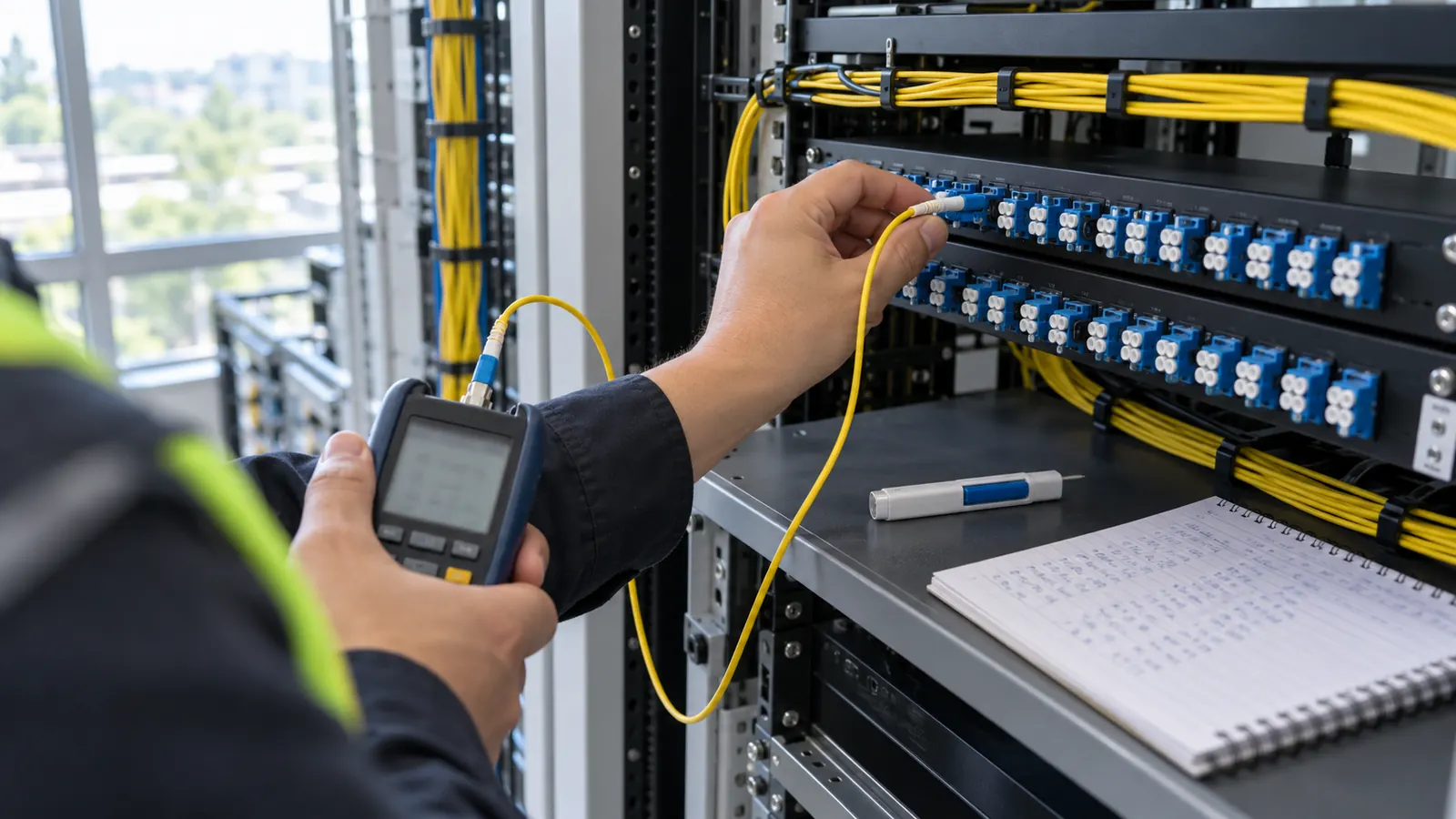
A stabilized light source and optical power meter compare received power through the link with an established reference. An optical loss test set, or OLTS, combines those functions into a testing system. We specify the reference method and compatible test cords before field work. A changed reference changes the meaning of the displayed loss, even when the fiber under test has not changed.
The 1-cord reference method is a common choice where the interfaces permit it and the applicable procedure calls for it. Other methods change which connections are represented in the measurement. Record the method used. We require the test diagram to identify the included end connections so a reviewer can compare the measured path with the budget without reconstructing the technician's setup.
Protect the reference: If a test cord or the source connection changes, stop and verify the reference under the instrument's procedure before collecting more acceptance results. Keep the original failed record when a repeat test follows corrective work.
Cleanliness affects the setup as well as the installed plant. We require inspection and appropriate cleaning of the test interfaces before establishing the reference, then verification that the reference cords are suitable for the measurement. A poor cord can consume apparent link margin. Repeatedly reconnecting it until a favorable number appears conceals uncertainty rather than resolving the cause.
Match the wavelength and fiber type
Single-mode testing at 1310 and 1550 nm produces separate results that must be compared with their corresponding limits when both wavelengths are required. Multimode measurement falls under IEC 61280-4-1:2019+AMD1:2021, Installed cabling plant, Multimode attenuation measurement, consolidated edition 3.1, published December 9, 2021. Its launch-condition requirements include encircled flux. We keep those multimode requirements out of single-mode setup instructions.
The record must preserve the test identity. We want the fiber identifier and endpoints tied to each wavelength result, with the reference method and instrument information available in the native report. Our preferred OLTS-first acceptance approach has a limitation: it measures total loss without locating the event responsible for an excessive result. That is where diagnostic testing becomes necessary.
Use OTDR traces to locate the loss
An OTDR launches pulses and analyzes returned light to map events along the fiber. It can identify where a loss occurs and reveal reflective interfaces, whereas the source-and-meter result measures transmission between the defined endpoints. Fluke Networks' OLTS & OTDR: A Complete Testing Strategy describes these as complementary functions. We use the trace to investigate the path rather than silently substitute it for the specified insertion-loss test.
Interpret event loss with its measurement limits
Dead zones can hide or merge nearby events. Launch and receive fibers help expose the link's end connections, but their suitability depends on the instrument settings and the path being tested. We retain those settings with the trace. A tidy event table without a readable underlying trace leaves the owner unable to judge whether the instrument resolved the connections it claims to measure.
A splice can appear to gain power in one direction because the adjoining fibers return different amounts of backscatter. It creates no optical gain. Where bidirectional splice evaluation is specified, combine the corresponding event measurements from both directions using the prescribed method. Our OTDR acceptance and splice-loss guide develops that event-level review and the evidence needed to resolve a disputed splice.
We investigate a failed total-loss result by confirming the test setup before ordering physical rework. Then we correlate the trace with the splice schedule and inspect the indicated location. After a correction, repeat the applicable end-to-end measurement and preserve both records. Closing the defect requires evidence that the repaired path meets the original acceptance criteria, not only that one event looks better.
Release decisions for owners and designers
For network owners: Require a path-specific acceptance limit and an equipment compatibility check before accepting a pass label. They answer different questions. Keep the native test files linked to the accepted fiber schedule so operations can identify what changed when an equipment replacement or repair consumes additional margin.
For designers: Resolve missing component data before issuing the budget. Mark an unavailable guaranteed loss as MISSING rather than substituting a familiar typical value, and require the selected product's documentation to close that gap. We recommend checking proposed patching changes against both the longest route and the shortest operating path before approving the revised connection arrangement.
For acceptance teams: Use OLTS results for the specified end-to-end loss decision and OTDR traces for the required event characterization. Reconcile every exception with the approved specification. We would retain a failed record with its corrective action rather than deliver a folder containing only favorable retests, because the owner needs to understand how the final configuration was established.
Draftech's engineering is 100% in-house; our full turnkey construction is delivered by Draftech-managed subcontract crews under Draftech's QA/QC. We connect the optical budget to the construction package so an added connection has an accountable design decision behind it. The Draftech partner team provides that delivery context, and owners can discuss a fiber acceptance scope when the test boundary or equipment requirement remains unresolved.
For a qualifying route that needs its engineering basis established, the free engineering offer covers the first 20,000 linear feet at no cost, from feasibility and field survey through permit approval. The owner reviews each request before Draftech commits the package. That gives the route's optical assumptions a place in the engineering discussion before they become acceptance disputes.