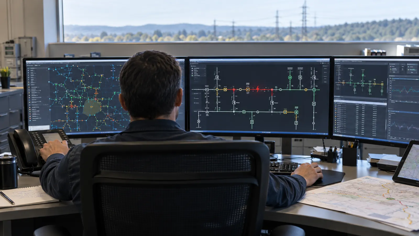
An automated tie switch can be installed exactly where the drawing shows it and still have no usable restoration path. The adjacent feeder may lack capacity, or a field change may have left the connectivity model describing a circuit that no longer exists. We start with those dependencies because they decide what the physical upgrade must accomplish.
For utilities and electric cooperatives, the practical question is how to turn an approved restoration concept into equipment locations that can be built and maintained. Our focus here is the field package and its records. The utility and its automation specialists establish the operating logic and electrical operating limits.
What FLISR does after a feeder fault
Fault location, isolation and service restoration, or flisr, coordinates distribution devices to identify a faulted section, isolate it and restore eligible healthy sections. Its 3 functions depend on usable switching boundaries and an available supply path; customers within the isolated section remain without service until the fault is addressed.
The sequence begins with protection. A protective device interrupts fault current, and the restoration scheme uses available indications to determine which section needs isolation. FLISR does not repair the damaged conductor. We distinguish the location of a suspected faulted section from the exact physical damage location, which may still require field investigation.
Locate the section and establish its boundaries
A fault indicator can show that fault current passed its location, but opening the circuit requires a switching device. A recloser can interrupt fault current within its rating, while a sectionalizer works with an upstream protective device and generally opens during a de-energized interval rather than interrupting fault current itself. Device duties matter when the utility identifies the boundaries of an isolation zone.
Before our designers develop a pole arrangement, we need the owner to identify what the device at that location must do. A drawing labeled only as an automated switch leaves important questions unanswered about the installation. The approved equipment selection must tell us what needs mounting and how the control cabinet connects to the primary device.
To confirm isolation, the utility has to account for the possible supply paths. Opening the upstream side alone may leave a path from the adjacent feeder through a tie; the circuit arrangement and operating state determine whether that path exists. We want the construction documents to identify the actual connection points so the utility's specialists can reconcile their operating scheme with the installed plant.
Restore healthy sections through an eligible path
Consider an illustrative radial feeder with a normally open tie to another feeder. After a permanent fault is isolated, a healthy upstream section may be supplied again from its original source, while an eligible downstream section may be transferred through the tie. This describes a possible topology, not a switching instruction or a promised restoration outcome.
Before a transfer can be accepted, the utility's power-system specialists must check equipment ratings and acceptable operating conditions, including the effect of distributed generation where present. We use their accepted requirements as design inputs. A physical tie shown on a map cannot establish the electrical suitability of that transfer.
For technical background, the U.S. Department of Energy's report Fault Location, Isolation, and Service Restoration Technologies Reduce Outage Impact and Duration, published December 2014, describes distributed and centralized arrangements and the importance of communications during damaged-grid conditions. We use that historical report to explain the technology, not to forecast a particular feeder's results.
Centralized versus device-based FLISR
The architecture determines where restoration decisions are coordinated and what information must reach that location. Centralized schemes can use a distribution management system, including an advanced distribution management system, or another central controller. Device-based schemes place more decision-making at field controllers, which may exchange information with peers according to the chosen design.
With either architecture, our field package must provide accessible equipment sites and a communications design that reaches the required endpoints. The owner must define how the scheme responds when a device is unavailable, a communications link fails or an operator has deliberately blocked automatic operation for work.
The feeder arrangement the utility intends to operate gives us a basis for comparing the architectures. Procurement labels alone give us little basis for drawing a fiber route or allocating cabinet space. The table below shows the practical questions to settle with the automation provider before the physical design is released.
| Decision | Centralized scheme | Device-based scheme |
|---|---|---|
| Decision location | Central application or controller | Controllers at field devices or within a defined group |
| Information path | Device information reaches the central application | Required information passes among participating controllers |
| Network changes | Update the model used by the application | Review affected device relationships and scheme boundaries |
| Field design question | Where do endpoints connect to the central communications network? | Which devices must communicate with which peers? |
| Operating responsibility | Utility and designated automation specialists | Utility and designated automation specialists |
Centralized schemes and a maintained network model
A centralized scheme can evaluate restoration against a broader network representation when its application and inputs support that capability. This makes model maintenance an operating dependency. During design review, we need to establish how newly installed devices enter the owner's model and how construction changes reach the people maintaining the automation application before the equipment is enabled.
A switch symbol at the correct coordinates can still be connected to the wrong segment in the model. Even a normally open tie with the right asset number can have an incorrect connection relationship. In our review, we separate those electrical relationships from the map's appearance. Geographic accuracy and electrical connectivity answer different questions.
Device-based schemes and defined operating groups
Device-based arrangements can fit a bounded feeder group with agreed switching relationships. The utility's specialists define what each controller knows and how it coordinates with other devices. We translate the resulting physical requirements into installation details, keeping the boundaries of each communications connection clear enough for the construction team to build them.
When a feeder group expands, adding a tie or changing a source can alter the relationships that the original scheme assumed. The new hardware may look identical to equipment already installed, so the change needs review even when the mounting details stay familiar. Where future additions are expected, our approach is to reserve space and document connection points; the automation specialists handle future logic changes.
A limitation of our field package is that even complete drawings cannot resolve an unvalidated restoration scheme or insufficient alternate-feeder capacity. The utility needs to assign those questions to the appropriate specialists. Before committing construction scope, we work with the owner to separate approved operating requirements from assumptions still awaiting technical review.
Build the switching sites and communications together
The field design starts at the proposed sectionalizing and tie points. Our electric utility engineering work connects accepted owner requirements to distribution construction documents. Draftech International provides turnkey telecom and power infrastructure, with engineering performed 100% in-house and full turnkey distribution construction delivered through Draftech-managed subcontract crews.
Reclosers, switches and pole work
An automated device adds more than a symbol to the feeder map. Its installation can require a different pole arrangement or changes to adjacent attachments, with the design depending on the equipment configuration and existing conditions. We review the proposed assembly against field measurements before releasing a mounting detail that assumes space the pole does not have.
A technician needs to reach the cabinet safely for maintenance, regardless of whether its communications connection works. We want the survey to show the approach to the pole and the surrounding conditions, so the installation design addresses access without assuming that every roadside location can accept the same arrangement.
To make equipment responsibilities clear, our drawings should distinguish the primary device from its control cabinet and identify the physical wiring or conduit responsibilities specified by the owner. The recloser engineering discussion gives context for the utility's protection decisions; those approved requirements feed the physical package rather than becoming settings authored by Draftech.
Communications to every participating device
Communications often use fiber, but the appropriate medium depends on the architecture and the utility's requirements. Our route design needs to reach the actual endpoint at each participating device, beyond the nearest fiber route. A cable passing the pole still needs an approved connection into the control equipment, with ownership defined at that interface.
Two logical connections may share a single pole line or enclosure, leaving both exposed to the same damage. Before we describe mapped paths as redundant, they need review with the utility's communications team. That check matters especially where the communications route follows the distribution circuit it is intended to support.
Keep the device identifier on the communications drawing. In our drawings, the owner-approved identifier should match at the pole and the fiber termination so a maintainer can trace the connection without guessing which switch the drawing describes.
The control equipment also needs an appropriate power arrangement. The owner and its equipment specialists establish the operating requirements, including behavior during loss of normal supply. Our installation package carries those accepted physical provisions alongside the fiber connection, since the controller needs power to communicate.
Physical hardening and automation solve related problems. Our grid hardening engineering scope addresses the distribution assets supporting the scheme, while the utility decides which restoration functions to enable. The feeder prioritization questions in our distribution storm hardening guide help frame where an automation investment depends on other asset work.
Keep GIS connectivity aligned with construction
GIS records need to describe the network that exists after construction, including the connection relationships that affect switching. For our records handoff, the utility needs to identify which system owns each operational attribute and how approved changes move between systems. The GIS database may supply an operational model, but the two should not be assumed to update each other automatically.
Check the model against field identity
We start by comparing the device identifier on the field label with the construction drawing and the owner's asset record. All three need to refer to the same equipment. If they disagree, preserve the discrepancy and resolve it with the owner. Silently choosing the most convenient label creates uncertainty for the next maintenance visit.
When checking connectivity, we look beyond where lines cross on the map: a crossing can represent an intersection without an electrical connection. A relocated switch may also leave an outdated segment relationship in the database. We want the owner's accepted connectivity rules applied explicitly, with the utility confirming that the resulting network representation supports its intended operating topology.
Record the field change before closing the work order. A moved switch needs a corrected record at its installed location, with the changed connection relationship identified for the owner's model maintainer.
Our proposed closeout should let the owner trace each changed device back to the accepted construction revision. Photographs help establish the installed arrangement, while redlines explain what changed from the issued design. Before construction begins, we want agreement on the evidence required for acceptance so the crew knows what to capture while the work remains visible.
Separate installation acceptance from automation acceptance
A physical installation can be complete while operational acceptance remains open. We keep the utility's automation review distinct from acceptance of the pole work and communications construction. Where the contract includes fiber test records, their identifiers should match the installed route; a passing cable test by itself does not establish that the restoration application will operate correctly.
For operational release, the utility's designated specialists verify the scheme under the required conditions and decide when automatic operation is permitted. We provide construction records and resolve physical discrepancies within our scope. The acceptance boundary should be written into the work package so nobody mistakes completion of civil or line work for permission to energize or enable automation.
Measure the restoration result without promising a percentage
Reliability benefits depend on which customers regain supply and which remain in the faulted section. The DOE report evaluates customer interruptions and customer minutes of interruption across reported events. Those historical results illustrate what can be measured. They do not establish a guaranteed improvement for a different utility's feeder or for a proposed construction package.
Before evaluating results, we would settle what the event records need to capture. The utility needs enough information to distinguish successful transfers from cases where the scheme was unavailable or correctly refused a transfer. That distinction matters when a blocked operation reflects an electrical constraint rather than failed equipment, because the corrective action would be different.
SAIDI expresses average interruption duration per customer over a reporting period, subject to the utility's reporting methodology. An individual FLISR event can contribute to that measure, but the feeder's annual result also depends on other interruptions. We would keep a construction acceptance record separate from a reliability claim until the owner has evaluated the operating evidence.
Customers within the isolated faulted section may still need physical repair before service returns. Some healthy sections may also have no eligible alternate source, so we would name both cases in the project objective. That gives the utility a realistic basis for deciding whether another tie or a different sectionalizing location deserves investigation.
Choose the field scope your utility can accept
For a co-op beginning with a bounded feeder group: establish the accepted restoration concept before releasing the equipment sites for construction. Our first field priorities would be resolving uncertain pole conditions and confirming communications endpoints. Device-based automation merits consideration where the utility's specialists can define and maintain the required operating relationships.
When extending centralized utility automation: require an explicit path from construction redlines to the operational model. At each changed site, our acceptance package would include identifier reconciliation, with the model owner named before work starts. The usefulness of wider network visibility depends on keeping that representation aligned with field changes.
If your utility records are incomplete: fund the survey and connectivity reconciliation before treating the existing map as a construction basis. For that work, we would resolve uncertain ties before finalizing their physical upgrades. Otherwise, an equipment package can advance through procurement while the utility is still determining how the proposed devices connect to the circuit.
Draftech's partner and delivery information explains the team behind this work. Active in 24 states. Available across all 50 U.S. states. For a scoped discussion, use our project contact page or email info@draftech.com with the available feeder drawings and the owner-approved physical requirements.
Our team can bring uncertain device locations and disconnected construction records into one coordinated field package, from survey and planning through construction drawings, permits and agency coordination. Draftech-managed crews deliver the distribution construction, and our team carries the installed changes into as-builts and closeout. The utility retains responsibility for automation logic, ADMS software and power studies.
Where the communications route qualifies, our free route engineering offer can support the field infrastructure behind the scheme: Draftech engineers the first 20,000 linear feet at no cost, from feasibility and field survey through permit approval. The owner reviews each request before Draftech commits the package. To prepare a scope for review, send us the utility-confirmed transfer requirements with the available site and communications records. Our team can then identify the equipment locations, communications endpoints and record corrections to include in the field package, with unresolved items assigned before construction release.