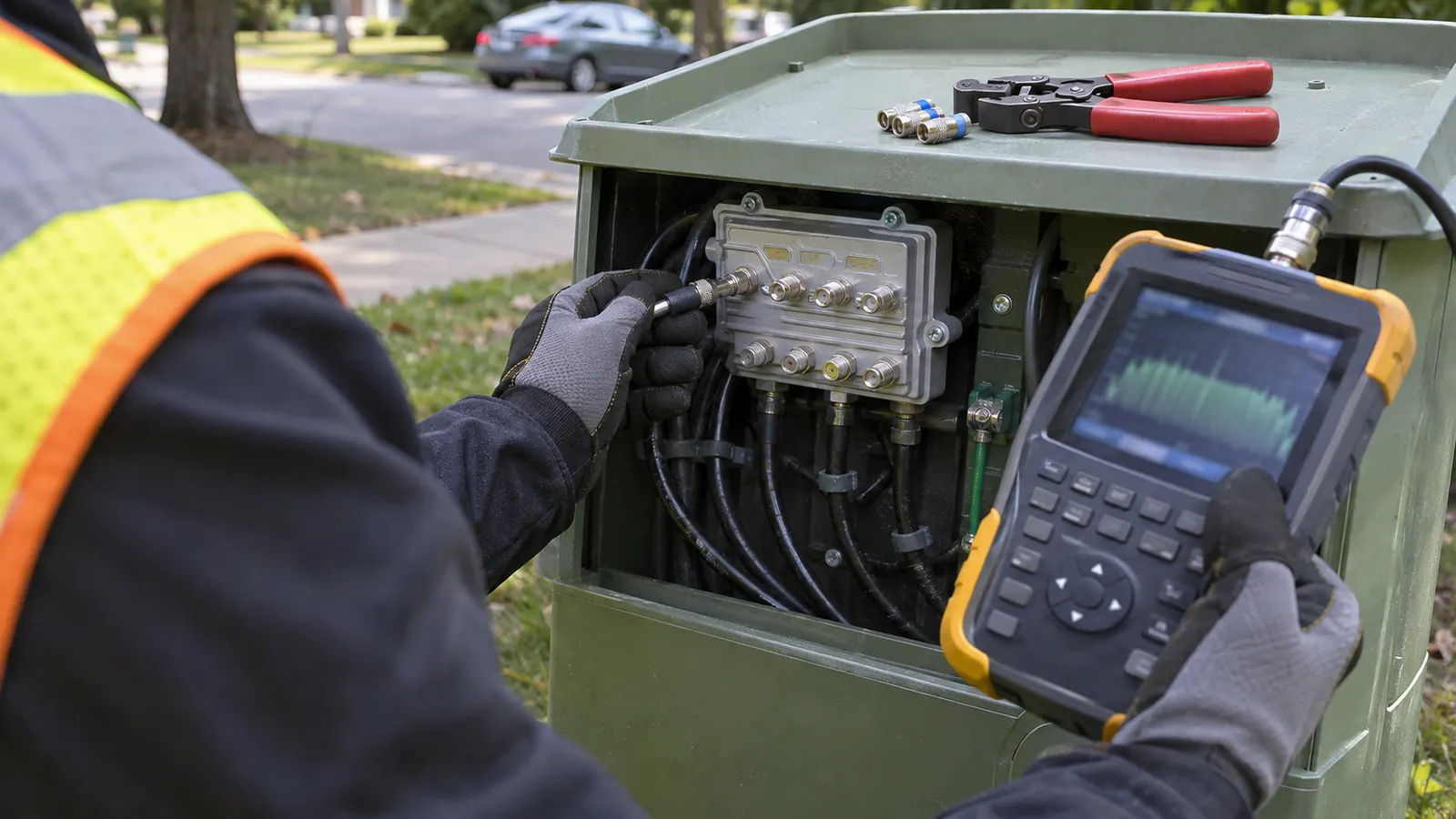
DOCSIS 3.1 frequency range: start with the band edges
The docsis 3.1 frequency range extends downstream from 258 MHz (108 MHz optional) to 1218 MHz (1794 MHz optional), according to CableLabs' Physical Layer Specification, CM-SP-PHYv3.1. Upstream top edges include 42 MHz for sub-split, 85 MHz for mid-split and 204 MHz for high-split. Installed plant determines which supported range can be used.
A spectrum expansion starts with a mismatch between the proposed band plan and the plant drawing. The drawing may show a continuous coax path while the equipment along it supports different passbands. That mismatch matters. An amplifier housing can remain in place through several internal changes, so its location and appearance alone tell our designers little about the signal path inside it.
Optional spectrum needs an explicit design decision
The optional lower downstream edge has a condition: CableLabs' CM-SP-PHYv3.1 associates 108 MHz support with an upstream upper edge of 85 MHz or less. That matters when comparing split choices. An operator cannot carry the lower edge into a high-split drawing simply because both figures appear in the same specification. Record the selected upstream and downstream boundaries together.
Separate capability from operating scope. The standard describes supported capabilities; the operator's band plan identifies the intended use. Our RF review needs both. A drawing that says only “DOCSIS upgrade” leaves the designer guessing about which components remain and which frequency-dependent values belong in the calculation, especially where branches have been rebuilt at different times.
A higher maximum frequency also says nothing by itself about the amount of spectrum assigned to a particular service. Keep those questions separate. Frequency limits describe the available engineering envelope, while the retained equipment and the operator's service requirements determine the proposed arrangement within it. Our concern here is the physical path that must carry that arrangement.
Read the route before choosing the replacements
Trace the coax path from the node through every active stage to the terminal passive path. Follow each branch. The hybrid fiber-coax engineering overview explains why the optical and coax portions belong in the same architecture decision, even when the immediate change sits entirely within the RF plant. A node boundary drawn in the wrong place can distort the scope of the review.
The inventory should distinguish confirmed equipment from inferred equipment. Our preferred starting point is a component record tied to the branch drawing, with the installed configuration stated explicitly and any unknown internal assembly left unresolved. Keep the uncertainty visible. Assuming that every similar enclosure contains the same module makes a tidy inventory and an unreliable design basis.
The comparison below turns the frequency choices into plant questions. It describes engineering checks rather than a universal replacement schedule. A component may remain only when its documented characteristics support the selected plan and its place in the cascade; the presence of a newer unit elsewhere on the branch provides no evidence about that component.
A split change reaches every directional path
For an upstream change, CableLabs' CM-SP-PHYv3.1 identifies the relevant top edges of 42, 85 and 204 MHz. The split determines where the plant separates upstream and downstream traffic. Changing it therefore reaches beyond the node to each directional device on the affected branch. Our design starts with that complete path, because a retained filter can prevent the proposed return band from reaching its destination.
Diplexers and installed amplifier configurations
Follow the filter path. A diplexer directs the lower and upper bands into their respective circuits. Its transition region needs room between the usable bands, and the selected arrangement must agree with the operator's frequency plan. A higher return edge cannot be treated as an independent setting while the downstream path and the installed filters remain assumed rather than identified.
Amplifier review must reach the installed module. The housing is only the enclosure. For our cascade analysis, the useful record identifies the forward and return paths and the characteristics of the configuration that will remain after the change. Where the proposed arrangement requires a different internal assembly, the drawing should distinguish that change from a complete location replacement.
| Design choice | Spectrum reference | Plant question to resolve |
|---|---|---|
| Retain sub-split | 42 MHz upstream top edge | Does the existing return path meet the operator's retained-band objective? |
| Move to mid-split | 85 MHz upstream top edge | Which diplexers and active return paths require a changed configuration? |
| Move to high-split | 204 MHz upstream top edge | Does every directional path support the revised upstream and downstream separation? |
| Use the baseline downstream upper edge | 1218 MHz | Do branch losses and retained passive characteristics support the proposed levels? |
| Evaluate the optional downstream upper edge | 1794 MHz | Which high-frequency component limits alter the cascade or node architecture? |
The frequency entries come from CableLabs' Physical Layer Specification, CM-SP-PHYv3.1, sections 5.2 and 7.2. The plant questions are our engineering interpretation of those choices. They deliberately distinguish a split change from a downstream extension: the work can overlap, but the reason each component needs review is different.
Node ports and branch boundaries
A node upgrade needs a port-by-port view of the connected coax. Branches differ. A common node enclosure does not establish that every output feeds the same downstream cascade or the same return-path arrangement. The node record should connect each RF port to its actual branch, with retained and proposed configurations shown together so an apparent gap in the drawing cannot conceal an incompatible filter.
For operators bringing that question to us, Draftech's HFC cable network engineering covers RF cascade validation and amplifier spacing analysis, supported by passive component assessment and node architecture design. Engineering is 100% in-house. Those activities connect a chosen band plan to the physical route, allowing component decisions to be evaluated against their effect on the entire branch.
Higher downstream frequency exposes passive constraints
CableLabs' CM-SP-PHYv3.1 gives 1218 MHz as the downstream upper capability requirement and 1794 MHz as an optional extension. Evaluating that extension means examining how the retained coax and passive path behave across the proposed band. More spectrum changes the loss calculation. Our passive assessment therefore needs frequency-dependent characteristics rather than a single nominal loss copied from an older drawing.
Taps need through-path and subscriber-path review
A tap participates in more than the connection to a drop. Its through path also affects the plant beyond it, and the coupling path determines what reaches the subscriber connection. Review both paths. A replacement that appears acceptable at the coupled port can still alter levels farther along the branch, so the passive schedule must remain connected to the cascade calculation.
Identify the installed assembly. A faceplate marking does not necessarily describe everything retained behind it. Our assessment needs enough detail to relate the visible component to the actual RF path, including any separate body or internal arrangement that remains in service. If that relationship is uncertain, carry the uncertainty into the design decision rather than assigning the most favorable available characteristic.
Other passives deserve the same discipline. A splitter or directional coupler can be easy to overlook when attention centers on amplifier locations, yet it still contributes loss and affects the branch response. Trace the signal through it. Retaining a component should be a documented decision about its suitability, not the accidental result of omitting it from the inventory.
Use evidence from the branch being redesigned
Branch measurement and ingress evidence should inform the retained-plant assumptions; the HFC coax upgrade engineering guide explains how those records relate to an upgrade decision. Evidence must belong to the relevant path. A clean observation from another branch does not establish the condition of the connectors or shielding on the route under review.
The limitation of our preferred inventory-led approach is that a complete component schedule cannot establish the condition of the installed coax. Records can support a calculation while leaving physical defects unresolved. Treat that distinction openly. Where the field evidence conflicts with the assumed response, revise the assumption before using the model to support retention of the affected passive path.
Separate component suitability from component condition in the review notes. This helps us avoid treating every disagreement as a bandwidth limitation when the actual concern may be the installed connection, and it prevents a condition concern from obscuring an independently unsuitable frequency rating. The owner can then see which uncertainty requires better records and which calls for a different design choice.
Recalculate cascade levels before retaining amplifier spacing
Taking the downstream path to CableLabs' CM-SP-PHYv3.1 upper edge of 1218 MHz requires the calculation to represent that proposed band. Existing amplifier spacing is an input to examine, not a result to preserve automatically. Our analysis follows the actual cable between stages and accounts for the intervening passive path, so a favorable level at an amplifier output cannot conceal a weak result farther downstream.
Show the assumptions behind the level
Keep the reference point explicit. An output level, an input level and a tap-port level describe different locations. Comparing them without their reference points can make a branch appear to gain or lose margin that the calculation never established. Label each location. The calculation should also identify the frequency associated with each reported value and the equipment configuration from which it was derived.
Frequency-dependent loss changes the relationship between the lower and upper portions of the downstream band. Equalization and the selected output characteristics must be considered together with that loss, rather than adjusted in isolation until the terminal level looks acceptable. Follow the full cascade. A local adjustment can shift the conditions presented to the next active stage and change the remaining analysis.
Preserve the calculation boundary. When an amplifier location moves, revise the connected branch calculation rather than editing only the adjacent span. Otherwise, the drawing can show the new arrangement while the level schedule still describes the old path.
Spacing and return-path choices must agree
The return path needs its own review. Changing a forward-path arrangement does not establish acceptable upstream behavior, particularly when the same project changes the split. For our designers, the revised branch record must make those dependencies visible. A proposed amplifier replacement should identify whether the decision follows from the downstream loss analysis or from the return-path configuration, even where the final equipment change serves both.
Longer cascades give more component assumptions a chance to influence the result. That is a reason to compare architecture options, not to prescribe an unsupported universal cascade limit. Keep the recommendation branch-specific. Our preference is to show the retained arrangement beside the proposed change and identify the assumption that drives the decision, so the operator can challenge it without reconstructing the entire calculation.
Engineering ownership matters at that handoff. The Draftech partner and engineering overview identifies the people behind our work; for the technical review itself, the useful deliverable is a consistent node-to-branch explanation. A calculation that cannot be reconciled with the drawing leaves the owner with unresolved engineering work, even when each individual sheet appears complete.
Keep fiber deep and DOCSIS 4.0 in the architecture decision
CableLabs' DOCSIS 4.0 Physical Layer Specification, CM-SP-PHYv4.0, covers Full Duplex and Extended Spectrum DOCSIS capabilities. These belong to the architecture discussion as DOCSIS 4.0 features, not as benefits automatically delivered by changing a DOCSIS 3.1 split. Name the intended architecture. A future-facing label cannot replace a documented decision about the node and the coax that remain.
Fiber deep changes the retained coax problem
Fiber deep moves the optical boundary closer to subscribers and can shorten or remove amplifier cascades, while leaving passive coax paths that still need assessment. The node anchors that boundary through its optical interfaces and RF ports, so its location and serving-area arrangement shape the branches the design must support. Our node architecture review should therefore compare usable branch arrangements rather than select a site from the optical map alone.
A shorter active cascade can simplify some RF constraints, but it also changes where optical service must reach and where the node must sit. That trade-off deserves a drawing. When the retained coax requires extensive changes, the HFC versus FTTH comparison provides the broader architecture context for deciding whether continued coax use still suits the operator's objective.
The immediate design should distinguish what must work at release from what is merely reserved for a later choice. Our recommendation is to show the proposed operating band directly on the branch documents and describe future compatibility only where the retained components support it. Avoid implied capability. A reservation on a drawing is useful only when the physical arrangement preserves the option it names.
Turn the DOCSIS 3.1 frequency range into a branch decision
For operators retaining the split: prioritize the downstream path that constrains the intended service. CableLabs' CM-SP-PHYv3.1 optional 1794 MHz upper edge is a candidate for evaluation, not a reason to replace every component indiscriminately. Start with the branch evidence. A retained-plant recommendation should identify the components that support the chosen band and leave unresolved components visible for the owner.
For designers changing the split: establish the complete directional path before finalizing the passive schedule. Our recommendation is to resolve the diplexer arrangement at each affected active location and reconcile it with the node ports. Close the loop on the drawing. An upstream proposal that stops at the node leaves the rest of the plant's compatibility unanswered.
For owners comparing architectures: use the cascade result to decide whether the next design should retain the amplifier arrangement or move the optical boundary. The decision needs a stated objective and a defensible physical path. Send the serving-area drawing and proposed band plan through our project contact page, or discuss the engineering question at info@draftech.com.
Uncertain diplexers and poorly documented passive paths make a spectrum decision difficult to defend. Draftech can address those design questions through RF cascade validation, amplifier spacing analysis, passive component assessment and node architecture design. For a qualifying route, our free-design offer covers the first 20,000 linear feet at no cost, from feasibility and field survey through permit approval; the owner reviews each request before Draftech commits the package.