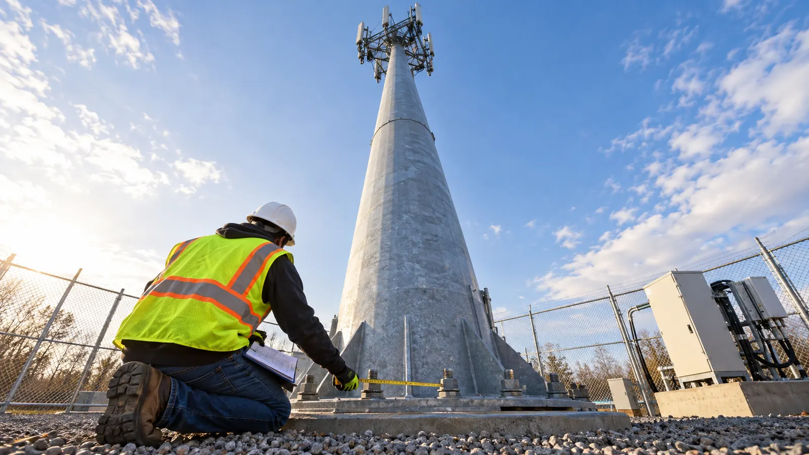
What a monopole tower changes about a cell site
A monopole tower is a freestanding antenna support built around 1 vertical shaft, usually assembled from tapered steel sections. Unlike a self-supporting lattice tower or guyed mast, it carries loads through a single shaft to its foundation. Concealment describes its appearance and can be applied to a monopole.
The narrow shaft can make a parcel look generous on a concept drawing, even though equipment still needs ground space. Add the access needed to replace an antenna, and that apparent surplus can disappear before the fiber entrance has a place to go. We lay out the usable site before choosing the tower.
This comparison treats concealment as a design choice that can overlap the structural families. A monopine, for example, can use a steel pole hidden by simulated bark and branches. Valmont Telecom's Olympus product range distinguishes monopole, self-supporting and guyed structures; Sabre Industries' Concealed & Decorative Structures range illustrates the separate appearance question. The concealment becomes part of the loading we evaluate on the underlying support.
For an owner choosing among these designs, we separate the radio requirement from the available land. Coverage determines the antenna arrangement, while the permitted configuration depends on the parcel and its approvals, which can rule out an otherwise suitable support before detailed structural analysis begins. Our comparison starts with those requirements, rather than a catalog photograph.
The footprint includes space outside the fence
Even when a tower fits within the permanent footprint, construction access can rule it out because the crane needs working room. A foundation can sit inside a lease boundary while the lifting position needed to assemble the shaft extends onto land the owner cannot use. Our concept review draws that temporary working area separately so the owner can secure access before committing to the layout.
Guyed structures make this distinction especially clear because their support extends outward to anchors. A lattice tower occupies land at its separated legs, while a monopole concentrates its support at one base. Concealment can enlarge the antenna envelope without changing the underlying support type. Drawing those extents lets us compare the land each candidate needs, including areas outside the equipment fence.
Reserve a usable expansion arrangement
Empty space tells us little about future colocation without a defined equipment scenario. We ask where the proposed antennas attach and how their cables reach the ground, because both choices affect the loading that the structural engineer must evaluate. The owner can reserve an elevation for expansion, but its usable capacity remains unverified until that loading is checked.
Cable entry deserves attention early because an internally routed pole can have room at antenna height but an unsuitable entry opening at the base, and a new opening changes a structural detail that must be reviewed before anyone cuts steel. We also check whether the compound can accept the associated ground equipment without blocking maintenance access.
Read the foundation with the tower
The first layout needs to account for the foundation, whose design depends on soil conditions and the load delivered by the support, so a small visible shaft does not establish a small excavation or prove that an existing foundation can accept another tenant. When we request the foundation records, we identify any gaps that still need investigation before the foundation can be evaluated.
Field verification can reveal errors in an existing site's antenna inventory, including incorrect removal notes. Equipment shown as removed may remain on the tower, and a replacement radio assembly can change wind demand even when it weighs less than the equipment being replaced. We reconcile retained equipment with the proposed configuration before counting any apparent spare capacity.
Zoning approval follows the proposed site
Concealment does not assure approval; land-use review follows the proposed height and appearance at the particular site. Setbacks and review paths depend on the applicable requirements, so our screening checks the parcel's conditions before treating an attractive rendering as a workable design. A screen that resolves a visual concern can still leave an access or setback conflict unresolved.
The lease exhibit should also agree with the physical design. On a guyed site, remote anchors need appropriate land rights; on a lattice site, the foundation arrangement must fit the authorized area. We flag a mismatch while the layout can still change. Our service-area directory gives owners a starting point for discussing the relevant project location.
Compare the four cell tower designs
The comparison below separates physical arrangements from capacity claims. Each design still needs analysis to establish an allowable height or tenant count for the specific structure and its site conditions, so we use this table to screen layouts before developing a candidate against actual equipment loads.
| Design | Structural arrangement | Land and appearance | Colocation review | Fiber entrance concern |
|---|---|---|---|---|
| Monopole | Single shaft with section joints and a foundation connection | Concentrated base; equipment compound and working access still required | Shaft, mounts and foundation must accept the proposed loading | Coordinate base openings with foundation and cable routing |
| Self-supporting lattice | Braced framework transferring loads through separated legs | Wider support base; exposed framework affects visual review | Check individual members and connections, not just overall geometry | Keep conduit clear of footings and leg access |
| Guyed | Mast stabilized by tensioned guys connected to remote anchors | Support system extends beyond the mast and equipment compound | Model the mast with the guy system and anchor conditions | Route around anchors and preserve inspection access |
| Concealed or stealth | Antennas screened by a designed enclosure or decorative treatment | Appearance must match the approved concept | Check the support and concealment assembly together | Fit the cable entrance without compromising concealment details |
Monopole tower: concentrated support on a constrained parcel
Steel monopoles commonly use tapered sections joined by slip joints or flanges; Sabre Industries describes both in its Monopoles product overview. Those joints form part of the structural load path as antenna mounts deliver loads into the shaft and down to its foundation connection. We favor this arrangement where a broad support base conflicts with the parcel and the required equipment fits the proposed pole.
Our preferred compact layout has a limitation: a monopole concentrates demand in the shaft and its connections, which can leave little flexibility for later equipment changes. Moving an antenna farther from the shaft changes the forces its attachment must carry. Our analysis therefore accounts for mount offsets using the proposed geometry rather than the antenna's weight alone.
Our monopole structural analysis discussion follows that load path through the shaft to the foundation. For selection, the practical question is whether the proposed configuration works without relying on unverified future reinforcement. We also want the erection approach checked against access, because long pole sections must reach a usable lifting position.
Self-supporting lattice: distributed support and exposed connections
A self-supporting lattice tower uses a braced framework whose legs deliver loads to its foundations without remote guy anchors. With multiple mounting surfaces, the framework can suit sites planned around equipment at several elevations. We favor examining it when the parcel can accommodate its base and the owner needs flexibility in the attachment layout.
A brace or connection can govern an upgrade even on a substantial-looking lattice tower, whose appearance cannot establish spare capacity. Our checks cover individual members, and we reconcile the installed framework with the records before relying on a model that may omit an undocumented modification. Missing member information needs investigation before the additional loading can be accepted.
Foundations also constrain the duct route. We keep access to leg connections available and coordinate underground work with the actual footing geometry, rather than treating the open space between legs as an unrestricted utility corridor. Our lattice tower structural review explains why member condition and connection details matter to modification decisions.
Guyed: a mast supported across a larger site
A guyed tower combines a slender mast with tensioned support cables connected to remote anchors. Because the anchors carry structural loads, their ground conditions matter to the supported system even when they lie well outside the visible equipment compound. We consider this arrangement where the owner controls enough usable land to protect the guys and maintain access.
For the land review, we follow the support cables from the mast to their anchors and check those locations against the land rights and planned access route. A drawing that stops at the compound fence can omit part of the structure's essential support. The anchors must remain accessible after construction, so a future driveway or utility trench proposed for that area needs review.
Guy tension affects how a supported mast behaves, so colocation requires analysis of the system as a whole. We need current condition information because an old plan may describe neither the installed equipment nor the state of the support cables accurately. When the necessary anchor area cannot be secured, we remove the guyed option from the parcel comparison.
Concealed: appearance adds another engineered assembly
Concealed designs hide equipment within an architectural feature or a decorative treatment such as a monopine, which may be supported by a monopole. We assess the selected concealment with the radio arrangement, since the enclosure's material and geometry must suit the antennas while meeting the intended visual treatment.
Branches and screens add loads to their attachments and the underlying support. Maintenance requires an opening with room to remove and replace equipment. A replacement radio may need more working clearance than the original assembly even if its operating position fits inside the approved outline. We check how equipment comes out without damaging the concealment and whether the replacement changes the visible treatment.
A concealed design is appropriate when appearance is a controlling site condition and the chosen treatment can accommodate the radio equipment. For zoning, we still need the actual review conditions: the appearance treatment alone cannot establish approval. The equipment arrangement must remain maintainable within those conditions, including room for the cables entering the concealed support.
Structural review and colocation must use the same layout
Tenant counts alone tell us little about an addition; the proposed tenant's equipment layout supplies the basis for evaluating it. A historical loading report may cover a different antenna arrangement, so we identify its assumptions and account for subsequent modifications before using it as the baseline for new calculations. Retained equipment belongs in that baseline even when the new tenant will not use it.
A tower shaft can pass its checks while the proposed platform or its connection needs modification. Approval of the mount has a limited scope, so we still verify the tower and foundation, and we match the attachment geometry in the calculations to the construction drawings so the installation package calls for the arrangement that was analyzed.
Freeze the equipment revision: Identify the proposed antenna and mount arrangement on the analysis package. If procurement changes either one, return the change to engineering before releasing the installation detail.
Antenna movement can govern the design, which is why structural review covers strength and serviceability separately. A support may have adequate member strength yet need further review for deflection or rotation at antenna height, particularly where the radio system requires tight alignment. We obtain those operating limits from the radio designer instead of assigning a blanket alignment capability to a tower type.
For clients bringing these inputs from separate teams, our wireless engineering services coordinate the support review with the proposed site arrangement. The purpose is practical: the structural model and construction drawings should describe the same equipment in the same location. A carrier's approved equipment list still needs to reach the engineering package.
Fiber backhaul has to reach an agreed handoff
A nearby fiber route gives us a candidate connection, not a confirmed service. Before we survey a constructible route into the compound, the operator must confirm service availability and agree on a handoff, because a line that passes the property may have no usable access point for the proposed service. That confirmation lets us develop the entrance around the foundation.
For a monopole, we coordinate the duct approach with the foundation and the approved shaft entry. At a lattice site, the route must avoid foundation conflicts and preserve access to the legs. A guyed site requires particular care around remote anchors, where excavation can interfere with support conditions well outside the equipment fence. We show these conflicts on the route drawing.
Concealment can restrict the cable entrance to a designed screen or opening. Before fabrication, we coordinate an opening that preserves weather protection and provides access for replacement cables when the equipment changes, without depending on an installer to cut a new path through the finished enclosure.
Define the boundary between backhaul and tower cabling
Backhaul carries traffic from the radio access network toward the core network, as described in Ericsson's mobile transport overview. Within the site, fiber between baseband equipment and remote radios may carry fronthaul, while other tower cables may carry power or radio-frequency signals; their function depends on the equipment architecture. We name the demarcation point so the outside-plant package ends at an agreed enclosure or equipment interface. Without that boundary, separate teams can each assume the other supplies the final connection.
Our wireless tower fiber connection survey guide develops the route from a confirmed connection to the compound handoff. The survey should establish where the path crosses the site boundary and how it reaches the designated entrance. A line ending at the fence leaves the most constrained part of the route undesigned.
Protect the entrance corridor: Put the proposed fiber entrance on the same plan as the foundations. Resolve an overlap before excavation, especially where an anchor or buried structural element extends beyond the visible tower.
Trace both fiber routes beyond the fence, where separate entrances can converge into a shared route. Where the network requires diversity, we identify shared ducts or other common segments that could interrupt both connections after a single excavation strike. Our route review distinguishes physically separate paths from separate entrances that lead back to the same vulnerable corridor.
Close out the installed arrangement
Before closeout, we reconcile field changes and resolve equipment substitutions against the design. Otherwise, the next tenant's structural review may inherit an antenna arrangement that no longer exists. The installed fiber entrance also belongs in the as-builts. The final records should show where the cable enters and which equipment the completed installation carries.
Acceptance of the tower installation and verification of the fiber connection are separate decisions, each requiring an identified responsible party. We coordinate the handoff with the serving operator so an accepted structure does not get reported as a working transport connection while the fiber service still awaits its own verification.
Choose the tower that fits the operating plan
For an owner with a constrained parcel: Start with the monopole, reserving the fiber entrance early as you test the whole compound layout. We recommend changing the arrangement when the pole cannot support the equipment scenario or the required construction access cannot be secured, even if its base fits neatly inside the lease.
When substantial colocation is planned: Compare lattice and monopole options using the same equipment assumptions. Favor the structure with verified mounting capacity at usable attachment locations and an evaluated load path to the ground, rather than choosing on a supplier's general description of suitability for multiple tenants.
For owners controlling ample support land: Include a guyed option when the remote anchors can be protected and maintained within secured rights. After the mast is erected, that land remains part of the structural system. The operating plan must retain anchor access, and future site changes must preserve it.
Where appearance controls approval: Develop the concealed option around the actual radio equipment and its replacement access. Require the visual concept and structural details to agree before fabrication. We recommend revising the enclosure when an antenna can fit only by blocking maintenance or extending beyond the intended approved appearance.
Draftech International provides turnkey telecom and power infrastructure delivery, with engineering 100% in-house and full turnkey construction delivered by Draftech-managed subcontract crews under Draftech's QA/QC. Our company overview explains that accountability. For a tower site, it connects field survey and planning to construction drawings, permits and agency coordination, followed by construction, as-builts and closeout. Send the proposed equipment arrangement to info@draftech.com to discuss the site.
For a tower requiring a new fiber route, our free design offer covers engineering the first 20,000 linear feet of a qualifying route at no cost, from feasibility and field survey through permit approval. The owner reviews each request before Draftech commits the package. We can then address the foundation conflicts and compound handoff as part of a defined route.