IN THIS ARTICLE
What a method of procedure controls
A method of procedure is the written, approved plan for 1 defined task on live plant, such as a fiber cutover or data hall cabling change, required before work starts. It identifies the affected connections, assigns responsibility, states the expected result of each step, and defines verification and back-out conditions.
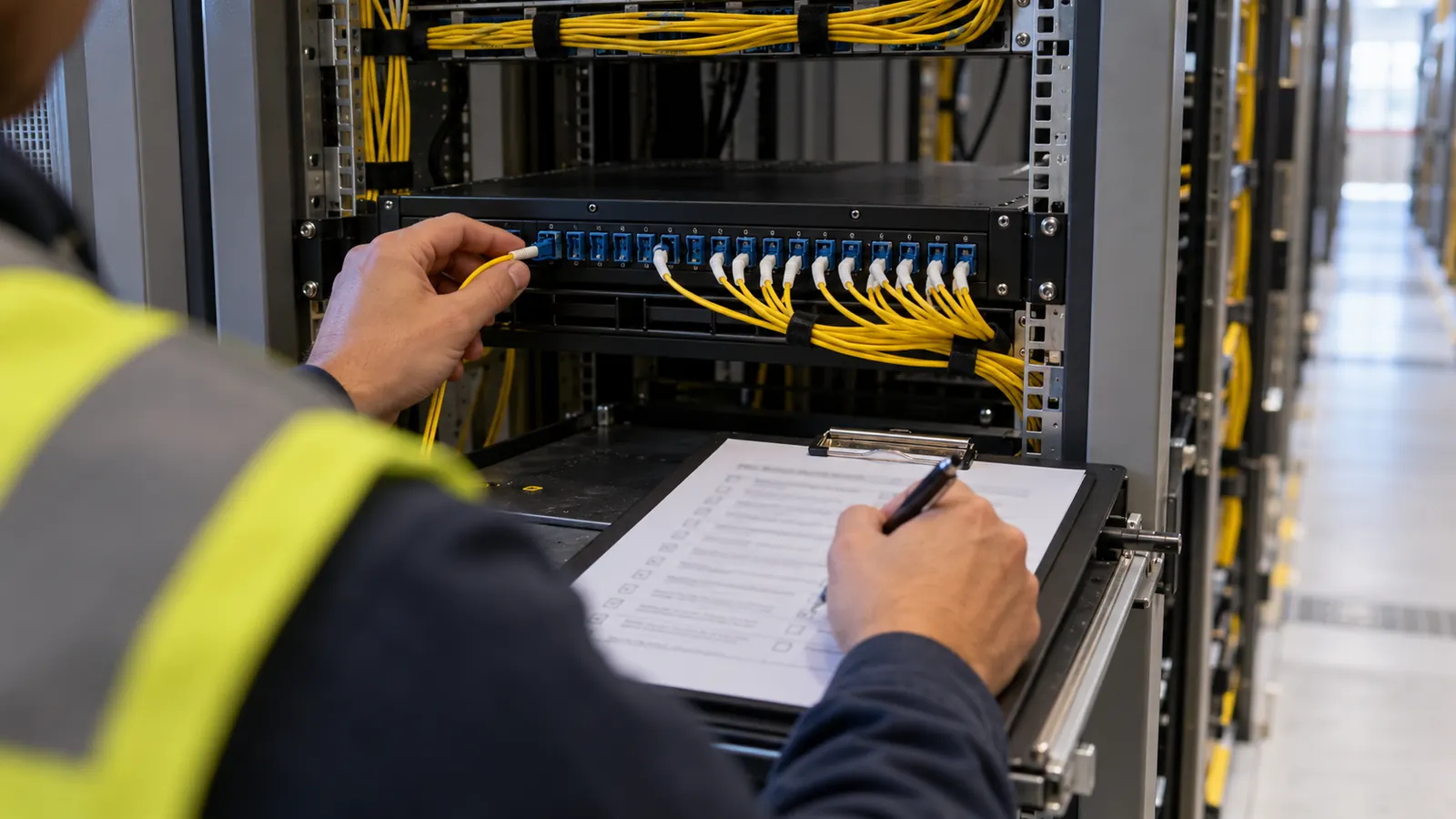
Picture a technician facing a populated fiber panel with an approved drawing open beside it. The panel identifier agrees, but the destination port is occupied, so the technician has to stop. A useful MOP makes that decision explicit before anyone disconnects a cord; it does not leave the technician to infer that the drawing must be more current than the rack.
We approach this subject from the design side. Draftech International supplies in-house engineering for telecom and data center work, while the facility's own cabling contractor performs the installation described here. The facility or network owner approves the MOP and controls the work window. Our drawings support the procedure under that division of responsibility, with the owner retaining authority over live services.
The task boundary has to be physical
One task needs identifiable endpoints. A description such as “move the fiber” leaves too much open. For a panel migration, we want the design to distinguish the existing termination from the intended termination, with the circuit association available to the owner's operations team. Equipment names alone cannot resolve a mismatch between a cabinet and the cable records inside it.
The scope also identifies nearby plant that remains untouched. A technician may need access through a rack carrying other services, and a patch cord can share a manager with connections outside the approved change. In our design review, we want that shared access shown in the work package so the owner can evaluate the exposure to adjacent services before releasing the task.
The owner determines service impact using information beyond the physical design. Although our drawings can show separate pathways and assigned fiber pairs, they cannot establish whether traffic has moved successfully onto a protection path at the moment of work. The MOP needs the owner's confirmation of the operating condition on which the proposed sequence depends. Without it, the physical drawing leaves a critical question unanswered.
MOP versus standard operating procedure
A standard operating procedure describes a repeatable way of doing an activity. Connector inspection and cleaning are examples. A MOP applies the relevant procedures to a particular connection under a particular authorization, including the conditions that allow the next action. We would expect it to reference the approved cleaning SOP rather than reproduce a disconnected set of generic cleaning instructions.
The difference becomes clear at the patch panel. An SOP can explain how an authorized technician inspects a connector before mating it; the MOP must identify which connection may be opened and who confirms that opening it is permitted. Referencing the SOP supplies the inspection method, while approval to open the particular live circuit still has to come through its MOP.
DataBank's published explanation, “Method of Procedure (MOP): What It Is, Why It Matters and How DataBank Manages It,” describes task-specific steps within data center operations. For cabling design, we make that principle concrete through endpoint records and expected results. The operating organization still decides the form of its approved procedure and the people authorized to execute it.
Design records before the work window
The drawing set supplies the physical facts that the procedure will use. We want discrepancies resolved while the proposed change is still on paper, because a technician should not have to redesign a pathway while holding a disconnected service cord. Once the existing condition is confirmed, the approved destination arrangement can be issued under a revision that the MOP can name.
Pathways and the limits of a floor plan
ANSI/TIA-942-C, Telecommunications Infrastructure Standard for Data Centers, published in May 2024, addresses data center infrastructure. Pathway drawings prepared to the project's TIA-942 requirements should show how the proposed cabling reaches its assigned termination. We need enough physical detail to distinguish the intended route from an adjacent tray, especially where separate paths are part of the owner's resilience design.
A floor plan alone may hide a shared bottleneck. Two routes drawn apart in plan can converge at a rack entry or pass through the same constrained opening. Before the work window is approved, we look for physical evidence of path diversity at those transitions. Checking them against the actual installation gives the MOP a route the contractor can recognize and exposes any shared opening that the plan view obscures.
| MOP component | Fiber cutover question | Supporting record |
|---|---|---|
| Scope and impact | Which connection moves, and what could be affected? | Existing and proposed endpoint schedule |
| Approvals and roles | Who releases the task and confirms each hold point? | Owner authorization and responsibility assignments |
| Steps and expected results | What physical state follows each action? | Port assignment and applicable splice plan |
| Verification | What proves the cabling and service are acceptable? | Approved test requirements and owner service checks |
| Back-out | How can the approved prior condition be restored? | Original connection map and recovery sequence |
| Sign-off | Who accepts the result and updates the record? | Test evidence and corrected as-built documentation |
Port assignments and splice plans
The port schedule connects the drawing to the rack. It should distinguish the present assignment from the proposed assignment, including the far end of the circuit. In our schedules, both views need to remain available through acceptance. If the schedule shows only the final arrangement, the person preparing the back-out sequence has to reconstruct the original patching from another source.
A splice plan matters when the task changes a splice rather than only a patch connection. Fiber identity must carry through the cable and closure records to the intended termination. When we check the design, we look for the relevant fiber identified within its cable. Repeated color sequences can make a shorthand instruction ambiguous at the tray, leaving the technician unable to distinguish fibers by color alone.
Our colocation inside plant engineering guide explains the demarcation and panel records behind that handoff. Those records also need agreement with the facility's cross-connect order: the ordered endpoints and delivery status must match the connection the owner intends to release for work. An order confirmation by itself does not establish the live port condition.
As-builts and TIA-606 labeling
ANSI/TIA-606-D, Administration Standard for Telecommunications Infrastructure, published in October 2021, provides the administration framework for identifiers and associated records. TIA's October 20, 2026 notice places the proposed TIA-606-E revision in recirculation ballot and public review. We distinguish a proposed revision from a published standard and use the edition adopted in the project's requirements.
For the MOP, a label is the field connection to that administration system. The identifier on the panel must agree with the referenced schedule, and the schedule must point to the same physical termination. We want any differences resolved before release, including a check of the existing condition in the field. Even when the labels and schedules agree with each other, they may describe an installation that has since changed.
That is why we treat as-builts as evidence to check, especially after intervening changes; the owner should identify the controlling revision and any outstanding field corrections that affect the proposed task. Through our data center fiber engineering, we develop the physical design records that let an owner compare an intended change against a defined starting condition.
A method of procedure for a fiber cutover
Consider an illustrative move of one duplex fiber circuit from an existing patch-panel position to an assigned replacement position. The identifiers below would come from the owner's actual records; this example supplies no executable port numbers or live-network commands. The old termination remains available for an approved return path. We use the example to show how a design becomes a reviewable sequence.
Scope, impact and permission to begin
The scope names the connection being moved and excludes unrelated patching. The owner determines whether interruption is acceptable or whether a verified alternate service path is required before cabling work begins. With that impact stated in the scope, we can check the proposed port assignment against the owner's service boundary. A conflict requires a design clarification from us before work proceeds; choosing a different port is outside the contractor's authorization.
Under the facility's rules, approval ties the work window to an authorized MOP revision. It also names the person who can release the first intrusive action once the prechecks are complete. A previously approved document can become unsuitable if the endpoint assignment changes before execution. The owner must resolve that difference before the contractor proceeds under the procedure.
Roles at the rack and in operations
The cabling contractor performs the physical work within its authorization. The owner's operations representative confirms the relevant network state and evaluates service checks. Our design role is to resolve questions about the intended physical arrangement. Writing those responsibilities into the procedure makes clear who must respond at each stage: the contractor can report that a connector is seated, while the owner must confirm whether the intended service has recovered.
The procedure should name who records results and who can call a stop when observations disagree with expectations. Where the owner requires an independent checker, that person's confirmation belongs at the relevant hold point. When we encounter an assignment such as “team to verify,” we ask who will make the decision that permits the next action. Naming that person prevents each participant from assuming somebody else has checked.
Actions paired with expected results
Precheck: The authorized personnel compare the panel labels and both endpoint assignments against the approved MOP. The expected result is an unambiguous match with the actual installation and a destination available for the planned connection. If the destination is occupied, the precheck has failed and work remains on hold while the owner and designer resolve the discrepancy through the facility's process.
Release: Operations confirms the starting service condition required by the procedure and authorizes the specified physical action. The expected result is a recorded release for the identified connection, not a general permission to rearrange nearby plant. In our review of the design handoff, we look for that release beside the action it governs. Its position should make clear when the technician has authority to disconnect, beyond any preparatory approval already recorded.
Move: The facility's contractor follows the approved sequence for the identified connection, using the applicable inspection and cleaning SOP. The expected physical result is the specified termination with correct routing and polarity. The authorization covers only that connection. If the contractor encounters unexpected resistance, an identity conflict or an unavailable destination, the task returns to the stated hold point for resolution before any correction is attempted.
Keep the previous connection traceable. Retain the original endpoint assignment in the work package until the owner accepts the new condition and releases the recovery arrangement. A final-state drawing alone cannot tell the contractor which previous port the approved back-out sequence requires.
Verification and back-out decisions
Cabling acceptance and service acceptance answer different questions. We specify the physical test boundary in the design package; the owner defines the service checks needed before accepting the change. Acceptance needs both results because a link indicator can appear normal while the wrong circuit is patched. Similarly, a satisfactory passive-fiber test leaves the owner with the separate task of confirming that the intended application is available.
Test against the approved boundary
The test plan should identify the connections included in the measurement and the applicable acceptance limits. For a passive link, the owner may require insertion-loss testing and OTDR evidence suited to that link's design. We avoid borrowing a loss threshold from an unrelated circuit. The actual component arrangement and the owner's specification determine what the result must demonstrate.
Our discussion of OTDR testing and splice-loss acceptance explains why a trace needs interpretation against the test method and link requirements. In the cutover record, each result must remain associated with the correct fiber identifier. If the trace filename leaves its endpoint association uncertain, a passing result in that file cannot establish acceptance for the connection that was changed.
The procedure must also distinguish offline testing from measurements permitted on an active network. The owner determines the allowed method and isolation conditions; the contractor uses equipment appropriate to that approved task. We would not recommend connecting a test source to an unidentified active fiber. The MOP should settle the test boundary before the work reaches the verification step.
Back-out conditions and the last reversible action
A back-out plan identifies the trigger for returning to the prior accepted condition and the authorized sequence for doing so. Triggers might include a failed service check or an unresolved mismatch that the owner cannot clear within the approved window. The plan names the person authorized to make that decision and preserves enough of the work window for recovery and confirmation.
Reversibility depends on the physical work. Returning a patch cord to a retained termination differs from restoring fibers after a splice change, where the previous connection may no longer exist in a form the contractor can simply reconnect. We ask that the design expose that difference before approval. “Reverse the steps” is inadequate when a step consumes the original condition.
The owner should identify the last point at which the approved recovery remains feasible and define what happens if work cannot progress beyond it. That decision requires the actual installation and the authorized work window, so a generic elapsed-time rule would be misleading here. When we review the endpoint records, we need to be able to follow the recovery sequence as precisely as the proposed move, including the connection that would be left in service.
After a back-out, operations must verify the restored service before closing the event. The recorded outcome should say that the proposed move was reversed and identify the condition left in service. For the design records supplied for review, we ask that the failed verification evidence remain associated with that outcome. Otherwise, a future design revision may assume the proposed panel assignment was installed merely because the change package exists.
Release sign-off and the design handoff
For facility and network owners: Approve the procedure against the service impact and the actual recovery path. Require a named authority at the release and acceptance points. If the records disagree with the rack, hold the intrusive work until the discrepancy is resolved. Approval should describe the installation that exists when the task begins.
For cabling contractors: Review the assigned endpoints against the accessible physical arrangement before accepting the execution sequence. Report conflicts through the owner's designated contact. An instruction that requires choosing an unassigned port needs clarification before work, even when the proposed substitute appears unused and the patch cord reaches it comfortably.
For designers and inspectors: Keep the previous and proposed conditions distinguishable through sign-off. We want the accepted test evidence tied to the installed identifiers, with field departures incorporated into the as-built record. Inspection establishes what was installed and documented for the owner to accept, while authority over network operation remains with the owner.
The final record names the accepted endpoint arrangement and any open exception the owner has explicitly retained. Our partner-led in-house engineering team supports the design documentation behind that review. For an upcoming cabling change, use our project contact page or email info@draftech.com to discuss the drawings available and the gaps that need engineering attention.
When an occupied port or an uncertain route prevents a clean MOP, the practical next step is to reconcile the design before requesting release. Our inside plant design service addresses that physical scope, giving the facility and its contractor a defined arrangement to review. The owner continues to approve the procedure and control the live work.
If the facility connection also requires a qualifying route, our free design offer covers engineering for the first 20,000 linear feet at no cost, from feasibility and field survey through permit approval. Before Draftech commits the engineering package, the owner reviews each request to establish whether the proposed route qualifies for the offer.