In This Article
What fiber to the antenna connects
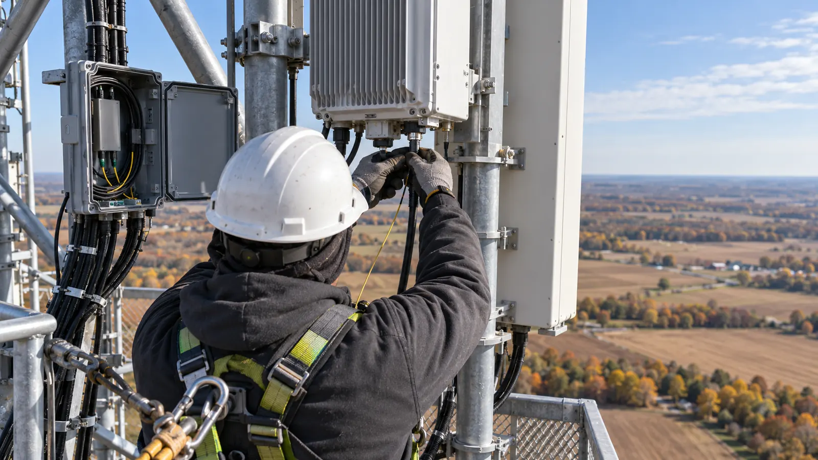
Fiber to the antenna (FTTA) carries optical signals from baseband equipment at a tower's base to radios beside the antennas, replacing long coax feeders. The path has 4 physical parts: a ground handoff enclosure, a vertical trunk, a tower-top junction and equipment jumpers. A hybrid cable also carries DC power.
The radio is the optical endpoint. Short RF connections can remain between a separate radio and antenna, so replacing the long feeder does not mean every coax connection disappears. We start the design at the approved baseband interface and finish at the radio connection, with the physical route between them fully accounted for. The carrier owns its RF requirements.
An FTTA link is part of fronthaul, the connection between baseband processing and radios, while backhaul carries site traffic toward the wider network. That distinction fixes the boundary of this article. The incoming transport route belongs in wireless tower fiber route design; here, we work through the equipment-side path after the ground handoff. Mixing those boundaries can leave a termination assigned to nobody.
For a tower owner, the cable arrangement changes what occupies the structure. For a carrier, it must match the selected optical interfaces and power requirements. Our drawings have to serve both readers without asking the builder to resolve their differences at elevation. A label such as "fiber to radio" leaves too much undecided when several sectors share the same trunk.
To make the connections traceable, we give every assigned fiber a destination and every installed cable a defined route with approved support details. Spare capacity receives its own designation in that same package. When an existing installation is being modified, we also identify what stays energized and what is removed, so the proposed condition cannot be mistaken for the installation sequence.
Follow the path from ground enclosure to radio
Ground handoff enclosure
Before assigning ports at the ground enclosure, we work out where it will mount and how the cables will enter. This is the transition from accessible equipment connections to the assembly going up the tower, so the layout has to leave room for maintenance. A door opening into another cabinet, or a tray that pulls on a jumper when moved, makes even a tidy installation difficult to service.
Where incoming fiber and outgoing FTTA connections occupy separate cabinets, our enclosure detail shows both: how fiber reaches the baseband equipment and where the outgoing fibers are patched or spliced. The connection schedule names each termination and its handoff responsibility so a generic enclosure label cannot obscure who handles it. Unused ports stay protected and clearly designated.
Vertical trunk and support route
Ordering the vertical trunk starts with measuring its route from the ground enclosure, around the turn onto the tower and through the upper breakout, including planned service slack. We use that route length for the assembly carrying the assigned fibers up the structure and, where the trunk is hybrid, the DC conductors serving the radios.
A junction mounted away from the climbing face can leave a cable short even when its length matches the tower height. The required approach direction of the end assembly can add another offset. Those dimensions go on our elevation so the order reflects the whole route. The support system must hold the cable without transferring its suspended weight to the connector or breakout.
Tower-top junction with surge protection
At the upper junction, the trunk divides into the connections that serve individual radios. The arrangement may use an enclosure or a protected breakout assembly, depending on the approved system. The detail locates the DC surge protection and its bonding connections explicitly. The optical fibers do not carry electrical surge current, but associated power conductors and metallic cable components need their own treatment.
With the equipment in place, can a technician still open the junction and replace a protective device without disturbing adjacent connections? We check that clearance against the installed layout. Water sealing also follows the selected assembly's installation instructions, including entry orientation. A protected connector loses that protection when an incompatible gland or sealing component is substituted during installation.
Jumpers at the endpoint
For the final jumper from breakout to radio, we identify the port before selecting a length. Mechanical fit alone leaves the optical interface, polarity and connector finish unconfirmed. Once those match the endpoint, the actual mounting arrangement determines the length needed for movement and service access without leaving loose loops around the antenna mount.
A technician following our cable map should be able to trace a radio connection all the way to its ground termination. Matching identifiers in the fiber schedule and test records make that possible without relying on color alone. Antenna placement and mount changes belong in macro cell antenna upgrade design; the FTTA detail follows the approved equipment position and documents the connections that position requires.
Make the cable design choices together
| Design choice | What controls it | What the package must show |
|---|---|---|
| Fiber count per radio | Approved optical interfaces and spare policy | Assigned fibers and reserved positions |
| Hybrid or separate cables | Power needs, routing and maintenance access | Actual assembly sizes and breakout locations |
| Connector protection | Port interface and environmental exposure | Mating components and inspection requirement |
| Optical loss budget | Selected optics and complete passive path | Allowable losses and acceptance method |
| Mechanical routing | Bend limits and approved cable supports | Turns, slack storage and support details |
| Grounding and structural loading | Electrical design and tower assessment | Bonding details and installed cable inventory |
Fiber count per radio
How many fibers should the trunk carry? We start with the carrier's approved interface schedule, because FTTA radios have no universal strand count, and add the spare capacity required by its policy. A duplex optical connection uses separate transmit and receive fibers; a supported bidirectional connection can use one. Neither arrangement should be assumed from the radio quantity alone.
An unused strand may reach an available breakout position, or it may remain unprepared inside the assembly. Our schedule distinguishes those conditions because they give the owner different expansion options and require different termination strategies. If the next equipment change requires opening or replacing the trunk, the design should say so instead of treating every unused strand as immediately usable capacity.
Assigning the complete trunk before selecting its final assembly works best for us, provided the carrier has settled the interface schedule. A later radio change can invalidate those assignments even when the physical cable still fits. We flag unresolved interfaces on the design issue and close them before releasing the affected connections for construction.
Hybrid versus separate fiber and power cables
A hybrid cable packages optical fibers and DC conductors in one assembly. Separate cables let the optical and electrical runs be selected and serviced independently. In our comparison of the installed arrangements, a single hybrid jacket may simplify the vertical route. The breakout still needs room, though, and its dimensions can determine the enclosure entry or support selection. A limitation of the hybrid arrangement we recommend where routing favors it is that spare fibers alone cannot support another radio without sufficient DC capacity.
Separate runs can suit an installation that retains a usable optical cable while changing the power feed. They also create more individual routes to support and identify. Our comparison includes the cable diameters and attachment positions, because counting jackets alone cannot establish which option presents less structural demand. We also check whether the selected route permits replacement without moving another carrier's equipment.
On the electrical side, conductor selection depends on required current and permissible voltage drop over the actual route. We calculate those separately from fiber capacity and coordinate electrical protection with the approved equipment requirements. A hybrid assembly must satisfy both disciplines, and its apparent spare optical capacity does not establish spare electrical capacity for another radio.
When cable selection keeps changing because the equipment layout and power design disagree, our wireless engineering coordination brings those inputs into the same drawing issue. Resolving that interface during design gives procurement a defined assembly to price and supply, and gives the builder a route that accommodates its physical requirements.
Connector protection and end-face inspection
A dust cap protects a disconnected end during handling, but the optical contact surfaces still need inspection when it comes off, even immediately before mating. For outdoor assemblies, our specification also identifies a compatible sealing system, the mating interface and the required inspection method before anything reaches the tower.
IEC 61300-3-35:2022, "Visual inspection of fibre optic connectors and fibre-stub transceivers," is edition 3.0, published September 16, 2022. It addresses end-face inspection. We use its criteria within the specified inspection process and keep the inspection record tied to the connector identification.
IEC 61300-3-35 distinguishes visual inspection from performance measurements such as attenuation and return loss. That distinction carries through to our acceptance plan, which specifies a cleanliness procedure alongside the optical measurements needed to establish performance. Where contamination is found, the crew follows the approved cleaning and reinspection process before making the connection; unresolved damage goes through the specified disposition process.
Loss budget for the complete passive path
Starting with the selected transceiver pair and the carrier's acceptance requirements, we build the loss budget from cable attenuation and the losses at every connector pair and splice. The defined link must include the full passive path the radio will use. If a patch lead falls outside the measurement boundary, the result describes only part of that path.
In the schedule, our design allowances remain separate from measured results, with the operating wavelength and applicable limit stated explicitly. The test plan then defines the reference method and which connections the measurement includes. A short tower run still needs this discipline, because connector contamination or a poorly seated interface can dominate the result even when fiber attenuation is small.
Keep the test boundary visible. Put the start and end connection identifiers beside the acceptance limit. A passing result is useful only when the owner can identify the installed path that was measured.
Fit the route to the structure
Bend radius and grounding details
The enclosure transition and top breakout deserve detailed drawings because these are places where we need to assess bends against the selected assembly's installation and operating limits. The installation limit may be more restrictive under pulling conditions. A route that works after the cable is seated may still be unsuitable for bringing a preterminated assembly through an entry or around a support.
On our elevations, slack storage occupies a defined location clear of access routes, with enough space to meet the cable's bend limit. A loop symbol in an otherwise blank space would leave that fit unresolved. Tie pressure and support compatibility also belong in the installation requirements. The cable must stay secure without jacket damage or localized compression at its supports.
For grounding, we identify each metallic component requiring bonding and its approved connection point. The DC surge-protection arrangement must agree with the site's grounding design, including the connection from tower-top equipment to the grounding system. Optical isolation leaves those obligations in place, so the builder receives the actual bonding details and conductor requirements needed to make the connections.
Cable count as TIA-222 loading
The Telecommunications Industry Association announced ANSI/TIA-222-I, "Structural Standard for Antenna Supporting Structures, Antennas and Small Wind Turbine Support Structures," on October 2, 2023. We identify the governing edition and site criteria in the structural package. The cable inventory forms part of that assessment, with each run's size and position coordinated to the configuration shown on the construction drawings.
Exchanging several coax feeders for a hybrid run may reduce the cable count without establishing that the structure has gained capacity. Weight and exposed area depend on the assemblies and how they are installed, including their associated attachments. Before accepting the proposed configuration, we reconcile those details in the cable schedule with the structural model inputs.
An old feeder left abandoned on the tower still belongs in the installed condition, even if the structural assessment assumed its removal. We mark retained and removed runs separately on the elevation so the construction scope agrees with the assessed configuration. The detailed structural workflow belongs in tower loading analysis for an antenna upgrade.
Put fiber to the antenna decisions into drawings and records
Working from the ground detail up to the upper junction, a builder should be able to follow our route without inventing a transition. The elevation locates radios and cable runs against the approved equipment arrangement and connects them to the ground detail. Each assembly designation on the drawing must match the material schedule so procurement and installation are working from the same cable selection.
Alongside the elevation, our connection records map each baseband-side port through its assigned fiber to the endpoint, including any intermediate connections. This gives the receiving crew the detail that an elevation cannot show clearly and keeps labels consistent through handoff. If the test crew uses different names from the drawing, the closeout needs an explicit cross-reference rather than an assumption that someone will recognize the circuit.
While the route is still accessible, record deviations such as a changed support position or substituted cable assembly. When a change affects the approved design, we require it to come back for engineering review. Photographs document the installation; any altered loading condition also needs approval through that review. The revised drawings and acceptance records must describe the same final arrangement.
At closeout, we tie inspection results to the installed connection map and record optical test results against the specified limits. Exceptions need a recorded disposition, and an unexplained missing test stays open until it is resolved. Owner acceptance should identify the released configuration, including any approved departures, so the next upgrade begins with a usable record instead of reconstructing the previous installation.
Release decisions for owners, carriers and builders
Tower owners: Require the final cable inventory to agree with the structural assessment before accepting the construction package. Check the removed-feeder scope closely. Your approval depends on the installed configuration, and a retained cable cannot disappear from the assessment merely because the new radio no longer uses it.
Carriers: Freeze the optical interfaces and DC requirements before releasing cable assemblies for procurement. We need the RF requirements from you, with the endpoint positions approved through your design process. If those inputs change later, bring the affected connections back for coordinated review before anyone substitutes a cable in the field based only on matching connector shapes.
Site designers and builders: Use the elevation and connection schedule together when planning the installation. Escalate a blocked route before moving the cable. Our team and delivery responsibilities explain who carries the engineering work; the project package must make the installation and acceptance responsibilities just as clear for the people receiving it.
Draftech International provides turnkey telecom and power infrastructure, with engineering 100% in-house and full turnkey construction delivered by Draftech-managed subcontract crews under Draftech's QA/QC. Through tower colocation engineering, we draw radios and cable runs at elevation, check the structure under TIA-222 and issue construction-ready drawings. Use our contact page or write to info@draftech.com to discuss an FTTA package whose drawings need to agree with the structural assessment and installed connections.
For a qualifying route associated with the site connection, our free design offer covers engineering for the first 20,000 linear feet at no cost, from feasibility and field survey through permit approval. The owner reviews each request before Draftech commits the package. We use that review to establish whether the proposed route fits the offer before defining the engineering work.