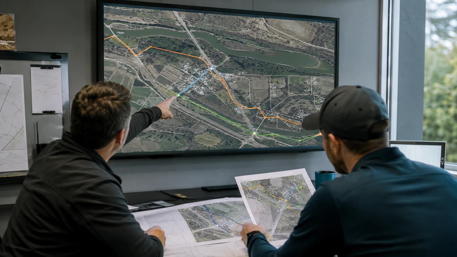
The shortest line between network nodes is often the wrong fiber route. A corridor that looks efficient in GIS can cross a protected resource, depend on unavailable pole space, share a failure point with the supposed diverse path, or else reach construction with no credible access method. Distance is only one input. The engineering decision is whether the entire corridor can be permitted and built, then tested and maintained through restoration.
This guide treats route selection as a controlled comparison rather than a drawing exercise. We cover the evidence needed at each gate, show how aerial and underground options change the risk record, and explain what must remain visible when a preferred alignment moves from HLD into LLD. The goal is a route decision that another reviewer can reproduce from source records.
What Fiber Route Analysis Must Prove
Fiber route analysis is the documented comparison of candidate corridors against engineering, property, environmental, permit, construction and optical constraints plus operating needs. A defensible analysis carries at least 2 alternatives until the decisive risks are verified, then records why the selected route is buildable and why each rejected corridor lost. That is the test.
A route is not proved by clean geometry. It is proved by connected evidence: endpoint requirements, existing plant, field observations, parcel and right of way information, pole or conduit availability, utility conflicts, crossing controls, environmental screens, construction access, optical continuity, resilience intent as well as maintenance access. We assign every source a date and owner because a stale pole record and a current survey are not equivalent inputs. The map should display confidence, not hide it.
The physical and optical models must use the same alignment. The current ITU-T G.652 recommendation, dated August 2024, defines characteristics for single mode optical fibre and cable, but it does not select a corridor or supply a project loss budget. We connect the chosen cable assumptions, route length, splice plan, passive elements, interfaces, design margin, and acceptance basis to the same controlled route revision.
Start with questions, not colored lines
The first route workshop should settle what the corridor must accomplish. Endpoints and required intermediate nodes come first. Then we define capacity intent, protection state, acceptable shared risks, future branch access, handholes or closures, power dependencies, ownership boundaries as well as the records operations will need; if those questions are open, drawing three alternatives only creates three unsupported guesses. We would rather show an unresolved decision than disguise it as a precise polyline. Name the source.
A candid limitation belongs in the route record: desktop sources cannot prove every field condition. Parcel layers can lag recorded rights, while public pole points may omit ownership or attachment data. Aerial imagery can miss recent road work. Environmental screening can identify a consultation path without resolving it. We label those gaps and convert them into survey, owner contact, title review as well as agency coordination tasks before the route becomes an issued design.
The Route Evidence Gates
Route analysis works best as a sequence of gates. Each gate can remove an alternative and add a condition, or else send the team back for better evidence. The table previews the record we use for a guide-level decision. It is not a universal checklist because owners and jurisdictions impose different controls. It maps decisions plus evidence together with unresolved exposure.
We release a gate only when its decisive evidence is available or the remaining uncertainty has an accepted owner and treatment. That distinction prevents a pending title question or unverified crossing from disappearing inside a broad preliminary label. The route decision log names the affected alternative plus its source, technical consequence, next action as well as approval authority. Reviewers can then separate a chosen risk from an overlooked one and reopen the correct segment when conditions change.
| Gate | Question | Minimum evidence | Release condition |
|---|---|---|---|
| Network intent | What must connect and survive? | Endpoint, capacity, protection, and branch requirements | Written route criteria |
| Desktop feasibility | Which corridors merit field work? | Base mapping, rights clues, crossings, resources, and existing plant | Viable alternatives retained |
| Field verification | What is physically present? | Pole, structure, surface, access, obstruction, and utility observations | Confidence gaps assigned |
| Owner and agency review | Who controls occupancy? | Current standards, application paths, property evidence, and permit matrix | Controlling sources named |
| Engineering comparison | Which route closes all disciplines? | Constructability, optical model, resilience, maintainability, and change effects | Preferred route documented |
| Design handoff | Can LLD proceed without guessing? | Controlled geometry, IDs, assumptions, exceptions, and source index | Revision basis accepted |
Desktop screening narrows the field
Desktop screening should eliminate obviously poor corridors while preserving meaningful alternatives. We overlay transportation ownership, parcels, known utility routes, hydrography, railways, structures, terrain, flood information, environmental resources together with existing network assets. The outputs are not construction drawings. They are candidate alignments plus crossing inventories, evidence gaps as well as a field plan. Every layer needs provenance so reviewers know whether it is authoritative or indicative, or else merely a lead.
Environmental screening starts early because a small alignment shift can change consultation or permit work. The U.S. Fish and Wildlife Service describes IPaC as a project planning tool that streamlines federal environmental review and helps identify sensitive trust resources. IPaC is screening evidence, not blanket project clearance. We preserve the project area used, the dated output, and the follow-up action rather than copying a species name into a generic risk column.
Field verification tests the desktop story
The field plan is driven by uncertainty: for aerial alternatives, it captures pole identity, apparent owner, existing communications space, guying, anchors, midspan conditions, road crossings, vegetation as well as access plus visible conflicts. For underground alternatives, it captures surface features, structures, route continuity, restoration context, congestion indicators, crossing approaches together with access constraints. Measurements and photographs stay attached to stable object IDs. Loose photo folders are not route evidence. Field evidence wins.
Underground conflict work has a hard safety boundary. OSHA 29 CFR 1926.651(b) requires estimated utility locations to be determined before an excavation opens and requires contact with utility owners under its stated conditions. A planning map does not replace locating and safe exposure, nor does it replace the contractor's excavation controls. Our route analysis identifies where uncertainty affects design; it never represents desktop lines as cleared excavation space.
Route control: attach each uncertainty to a location and owner, then name its resolution method plus decision date. A general note that says verify in field transfers risk without telling anyone what must be verified.
Compare Aerial and Underground Corridors on the Same Basis
Aerial and underground routes fail differently, so a simple cost or distance score is misleading. Aerial feasibility depends on pole ownership, attachment process, loading and clearance criteria, make-ready exposure, crossing geometry, vegetation plus access as well as line condition. Underground feasibility depends on usable pathway, congestion, depth evidence, utility separation, structures, bore or trench access, restoration, dewatering or rock exposure together with crossing permits. Both need rights and maintainability.
We normalize the comparison around the same outcomes: can the route acquire occupancy, satisfy engineering criteria, reach every required node, preserve the intended failure separation, support a practical construction method as well as remain accessible for operations? A mixed route often wins because the best answer changes block by block. The record must explain every transition between aerial and underground plant, including structure needs, cable handling, grounding interfaces where applicable, splice strategy as well as permit consequences.
Diversity is a physical claim
Two colored lines are not diverse if they share the same bridge, duct bank, pole corridor, railroad crossing, building entrance, handhole, sheath or an upstream node; we create a shared risk register and test normal plus protection states against it. Unknown third party paths stay unknown. They do not become diverse because a carrier quote uses different circuit identifiers. Where complete route disclosure is unavailable, the analysis states the limit and avoids an unsupported resilience claim. Keep it physical.
The resilience objective also changes what counts as acceptable. A route intended only as added capacity may tolerate exposure that a protected transport path cannot. A lateral serving a single distribution area is not judged like a trunk feeding several cabinets. We document each shared point's consequence plus available mitigation as well as who accepts residual exposure. That keeps route diversity from becoming a decorative line item.
Crossings and rights deserve early alternatives
A corridor can look settled until one bridge, controlled highway, railway, water feature or even a private parcel blocks the intended method. We identify critical crossings during desktop screening and carry at least one plausible alternative where the consequence is material, then ask the controlling owner about current criteria before LLD depends on the answer. The route file names the owner source and date. One county's detail is never treated as proof of another county's requirement.
Property rights need equal discipline. Public right of way on a base map does not prove that a particular facility may occupy it, and an existing utility line does not automatically grant space to another operator. We separate fee ownership and easement evidence from franchise or occupancy authority, license needs as well as open title questions. If legal review is outside engineering scope, the handoff says so plainly and identifies the decision that cannot close without it.
Carry the Selected Route from HLD into LLD
HLD should freeze route intent without pretending every construction detail is known. It establishes the corridor, topology, major nodes, candidate structures, crossing strategy, capacity basis, resilience assumptions together with unresolved constraints. The HLD and LLD boundary matters here: LLD must resolve placement and construction detail against the approved intent, not quietly choose a new corridor one permit sheet at a time.
The handoff includes controlled centerline geometry, route segment IDs, structure and node IDs, network relationships, source references, field confidence, property status, permit owners, crossing dispositions, cable assumptions, splice intent, optical inputs, exceptions plus open decisions. We also define what change triggers reanalysis. A shift that looks minor on a plan can alter parcel rights and environmental screening plus route length. It can also change a bore approach or shared risk. Revision control keeps those effects visible.
Budget work begins only after scope is comparable. The fiber network design cost guide explains why HLD, fielding, permitting, and LLD cannot be priced honestly as one undifferentiated line. Route analysis should tell an estimator which segments are aerial and underground, crossing-heavy, evidence-poor or dependent on third party work. It should not manufacture certainty where design is still open.
Candid check: our preferred route can still be wrong when the source record changes. Preserve the rejected alternatives well enough to reopen them without rebuilding the analysis from memory.
Fiber Route Analysis Decisions by Project Type
Greenfield FTTH build: favor the corridor that supports clean service area topology and practical branch access plus documented occupancy as well as repeatable construction. Do not optimize the backbone while forcing awkward distribution later. The FTTH HLD failure modes show how an early routing shortcut can move difficulty into cabinet placement and feeder structure. Keep the route decision tied to the full network.
Existing plant extension: verify the usable handoff point, cable and fibre status, pathway continuity, splice access, records, and optical effect before selecting the extension corridor. A line on an as-built is not proof of spare capacity or usable duct. If the existing record cannot be reconciled, route the investigation before routing the new cable.
Protected transport path: make shared risk the leading criterion. Prove entrances, crossings, structures, upstream nodes as well as maintenance access for both states. Reject a shorter option when it defeats the resilience objective. Flat decision: physical separation wins over map aesthetics, and any accepted common point belongs in the operating record with its consequence stated plainly.
Schedule constrained program: select the route with the most credible path through rights, owner review, field verification, and permits, not the route with the fewest mapped feet. If a decisive owner response is missing, show that dependency in the schedule and carry an alternate. A hopeful date is not evidence, and an unsupported release only moves the delay into LLD.
Draftech's in-house fiber network design team connects route evidence, HLD intent, field data, permitting inputs, LLD changes as well as closeout records under one accountable engineering model. When construction is included, Draftech provides full turnkey delivery through Draftech-managed subcontract crews under our QA/QC and safety oversight. The route remains traceable as field conditions change.
The recurring problems are not mysterious: unsupported occupancy, stale field evidence, hidden shared risk, crossing surprises as well as route changes disconnected from optical or permit review. We remove those gaps by giving every decision a source plus every exception an owner while every revision carries a consequence. Use the PON power budget calculator for preliminary optical screening. If an upcoming corridor needs an independent route review, email our fiber engineering team.