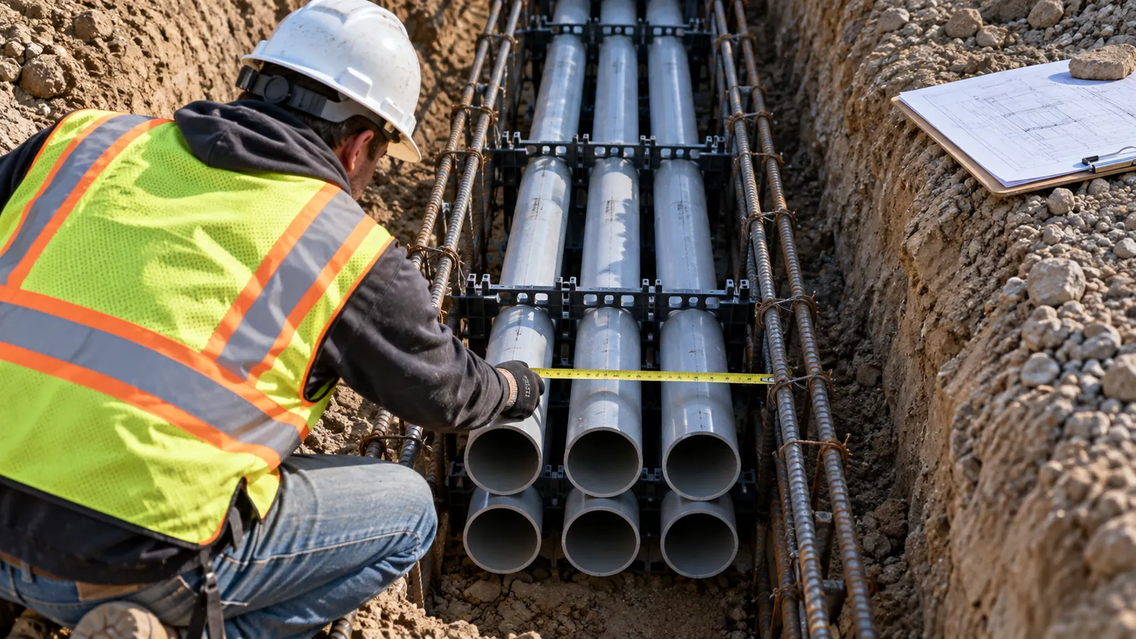
A duct bank can fit neatly on a plan and still leave the cable installer with an unusable bend. We treat the underground pathway as part of the electrical and communications design, because its geometry affects cable placement and the owner's ability to maintain the route after restoration.
This guide follows decisions from route investigation through as-builts. We explain where concrete encasement changes the work, how to establish cover and separation, and what must be checked while the conduits remain visible. The aim: a buildable package with clear inspection releases.
What an electrical duct bank must do
An electrical duct bank is a group of underground conduits arranged to carry power cables and, where approved, separate communications pathways. Its 2 basic construction forms are concrete-encased and direct-buried conduit banks. We design the arrangement around cable requirements and site conditions, then verify the installed geometry before concealment.
Start with the cable and its owner
The cable schedule comes first. We need the circuit duty and the intended cable construction before selecting duct size; an empty conduit that looks generous can still be unsuitable for the cable assembly or pulling equipment specified for that circuit. We first confirm the endpoints, since equipment entrances can constrain how the cable reaches them.
Spare capacity needs an assigned purpose. A spare power duct and a spare communications duct may have different destinations, and an unused opening at a manhole does not establish a continuous pathway to the next structure. We schedule spare ducts and verify their end-to-end identity during acceptance. That prevents future users from treating an unidentified opening as available capacity.
Establish the governing requirements
The 2023 National Electrical Safety Code, IEEE C2-2023, published August 1, 2022, covers underground supply and communication systems within its scope. We establish the applicable code and owner standards before detailing the bank, including where utility infrastructure transitions to premises wiring. At that boundary, we check applicable requirements rather than relying on a drawing label.
Our design basis identifies which authority accepts the installation and which owner detail governs each interface. If a utility standard and a civil drawing disagree, we resolve the conflict through the responsible designers before issuing construction instructions. That gives crews a coordinated section without incompatible dimensions to resolve in an open trench.
Design the electrical duct bank before excavation
The route needs both a horizontal alignment and a vertical profile. We compare the proposed bank against verified utility crossings, then check whether the proposed approach can reach its equipment entrance without creating an unacceptable bend. Because excavation and the finished bank occupy different envelopes, we show more than a centerline to resolve their fit.
Investigate the corridor
Existing records help target field investigation, but a line on a utility map does not establish the depth of a crossing. We distinguish surveyed features from inferred positions and identify where additional exposure is needed before the design can be released. We keep those uncertain positions visible in the review because moving a proposed bank deeper can create a new conflict farther along the route.
Reuse requires its own evidence. Our guide to an underground duct bank survey for telecom explains how to document an existing pathway before assigning it to new cable. For a new bank that connects to an old structure, we also verify the receiving wall and available entry positions. A vacant duct shown on a record may terminate somewhere the proposed circuit cannot use.
Choose encasement for a stated reason
Concrete-encased construction surrounds the conduit array with a designed concrete envelope. The engineer selects that envelope for the applicable loading and owner requirements, and specifies reinforcement where the structural design requires it. Before the concrete delivery reaches the trench, we need an inspection stage to check conduit restraint and confirm access for placing the concrete.
Direct-buried conduit banks use suitable conduit with specified bedding and backfill instead of a continuous concrete envelope. They still need a designed arrangement and installation controls, especially where compaction or trench conditions could distort the ducts. With direct-buried conduit, the cable remains inside a raceway, unlike direct-buried cable, so that raceway must stay open and usable after backfill.
Where route conditions change, we select the construction method per segment. A crossing may need a different treatment from the approach, but the transition must be detailed so that the change in support does not become a weak location. Correcting a misplaced conduit after encasement can require breaking out otherwise acceptable work.
Check the electrical assumptions
Cable ampacity depends on how heat leaves the installed system. We check the proposed duct arrangement against the electrical design assumptions, including the surrounding material and the effect of adjacent loaded circuits, rather than assuming that an acceptable cable size in another installation remains acceptable here. When the owner's requirement includes future loading, we evaluate that loading explicitly; the presence of empty ducts alone tells us little about the system's thermal capacity.
The specialist conduit and duct bank design package should connect these calculations to the issued sections. The construction team needs the actual conduit arrangement that was evaluated, and a proposed substitution must return to the designer if it changes that arrangement. These checks organize work after route and construction method selection.
| Design check | Concrete-encased bank | Direct-buried conduit bank |
|---|---|---|
| Spacing and cover | Confirm array and concrete envelope against the issued section | Confirm duct arrangement and specified bedding against the issued section |
| Pulling access | Evaluate the cable path through each structure entry | Apply the same cable-specific pulling assessment |
| Concealment release | Inspect restraint and geometry before concrete placement | Inspect support and geometry before backfill |
| As-built acceptance | Record installed position and duct proving results | Record installed position and duct proving results |
Set spacing, separation and cover on the sections
Conduit spacers hold the selected array during assembly and concealment. We specify them for the conduit size and installation method, with support intervals taken from the approved design and product instructions. Spacers hold geometry; we must design the permitted relationship between power and communications systems.
Keep the separation questions distinct
Spacing within an array allows the specified surrounding material to occupy the space between ducts and helps maintain the arrangement assumed by the design. Power-to-communications separation addresses a different interface. We show that relationship explicitly, whether the approved solution uses separate banks or an accepted arrangement within a coordinated corridor.
Where the NESC governs, use the applicable NESC 2023 provisions for the actual installation and document the basis on the design. We do not recommend treating a single clearance copied from an unrelated detail as a universal power-to-telecom dimension. We also check the utility's ownership requirements, which may call for a separate structure even where the proposed trench arrangement appears physically workable.
Joint construction needs named technical authority for each system. Our joint power and fiber construction guidance addresses that coordination problem: sharing excavation does not transfer responsibility for accepting the electrical design to the communications contractor. We resolve the arrangement at crossings and structure entries as carefully as along the straight run, where a typical section is easier to apply.
Measure cover from the right reference
Cover and trench depth are different measurements. The drawing must identify the surface reference and the buried element from which the required cover is measured, so an inspector can compare the installed work with the governing detail without guessing. Using the intended finished grade is essential here, since a future grading change can reduce cover even when the trench originally matched the excavation plan.
With the crossing elevations established, we develop the profile around those elevations and the applicable installation requirements. The bottom of excavation also depends on the bank height and the specified foundation or bedding, so a cover dimension alone cannot tell the excavator where to stop. At a constrained crossing, the designer must reconcile the vertical geometry before excavation proceeds through that location.
Make field verification possible
A useful section labels the conduit arrangement and shows the envelope that inspection must verify. We also identify where a typical section stops applying, such as a transition into a vault or an equipment pad with a restricted opening. We include specific details for those locations so the inspector can verify the exception in the field without having to reconstruct it from a designer's calculation file.
Before releasing a crossing for construction, compare its profile with the adjacent structure entries. A locally acceptable depth change can leave the next cable approach too steep or too tight, so review the connected segment rather than the crossing in isolation.
Locate pull boxes and manholes around the cable
Access structures belong where cable installation and future maintenance require them. We evaluate the complete pull between access points, because length alone does not capture the resistance created by the bends or the pressure a cable experiences as it passes around them. Since a straight run and a curved run behave differently, placing structures at equal intervals on a plan gives us no assurance of an acceptable pull.
Calculate the pull before fixing the structure
The pulling assessment uses the proposed cable and actual route geometry, with limits established by the cable manufacturer and applicable project requirements. We check pulling tension and sidewall pressure for the intended direction of installation, then confirm that the proposed bend radii work at the entries and underground. Changing the pull direction can change the result.
Equipment setup needs room outside the structure. A manhole placed where the plan has spare space may still be difficult to use if the cable reel cannot approach or the pulling equipment has no approved setup position. When we review the location with the owner, we account for the intended maintenance operation and check that access will remain practical after restoration.
Size the structure for its function
Pull boxes provide access for pulling where the approved design permits that arrangement; manholes can accommodate entry and cable handling when designed and operated for that purpose. We select each structure by its required function and loading, rather than treating the names as interchangeable size labels. Before anyone enters, the work also needs separate safety planning for entry; providing an opening in the ground is only part of making a structure usable.
Inside the structure, the cable must turn without violating its installation limits and remain supported in its final position. Wall entries need enough usable space for the specified arrangement, including future ducts that the owner intends to use. As we coordinate the duct schedule with the structure detail, we check entry orientation and duct counts, since reversing the entries still creates an installation problem.
Plan water control and acceptance
Duct routes can convey water toward a structure or building. We coordinate drainage and sealing with the site conditions and receiving owner requirements, and we avoid assuming that a conduit system will remain dry merely because its joints were assembled correctly. That review also needs to confirm that the selected cable suits its environment and that any discharge arrangement has an approved destination.
The Department of Defense's Unified Facilities Guide Specification 33 71 02, Underground Electrical Distribution, February 2026 with Change 1 issued June 2026, addresses duct preparation and cable pulling. It calls for observing specified cable bending radii and using cable-manufacturer-recommended lubricants. We use the project specification to define the actual acceptance procedure; a federal guide specification becomes a contract requirement only when incorporated.
Build, inspect and record before the bank disappears
Construction begins with the released design and the excavation controls appropriate to the work. Existing utilities must be addressed through the required locating and exposure process before excavation reaches them. We coordinate the construction sequence through our utility construction delivery, including the inspection releases that prevent concealed defects from becoming the next contractor's problem.
Assemble and inspect the open work
The trench foundation must support the specified bank. If excavation exposes unsuitable conditions, the responsible designer needs that information before the crew installs a different bedding arrangement on its own. We need to preserve the design assumptions through that decision because an improvised support condition can affect both conduit alignment and the behavior of the completed installation.
Draftech-managed crews assemble the approved conduits and secure the spacer arrangement under Draftech's QA/QC and safety program. Our inspection checks the installed geometry against the current drawing revision before concealment, with particular attention to entries and changes in direction. During assembly, the crew must also protect open ends against dirt or concrete, either of which can defeat an otherwise acceptable installation.
Photograph each concealed-work location with its structure or station reference while the measurement is still visible. A close-up without location context may show good workmanship yet fail to identify which section of the completed bank it documents.
Control the pour or backfill
For an encased bank, the placement method must keep the conduits from moving or floating while concrete fills the specified envelope. The approved restraint details need to survive that operation without damaging the conduit. At transitions, we follow the alignment farther down the open trench rather than judging the whole run from a neat array at the inspection point.
A direct-buried bank needs the specified backfill and compaction method to protect the conduits while supporting the surrounding ground. We establish the inspection release before the bank becomes hidden, then retain the acceptance records required by the project. Because concealment limits what we can verify later, any conflict the crew discovers during installation needs an appropriate design disposition for the revised detail before work proceeds.
Prove the pathway and retain the evidence
The completed ducts need the cleaning and proving specified for acceptance, with results tied to the individual duct between identified endpoints. A test record should distinguish an obstructed duct from a duct that was never tested. When a duct fails, we retain that result alongside the correction and repeat acceptance result, so the record explains how the failure was resolved instead of showing an unexplained pass.
Our as-built record connects the installed alignment to its elevations and identifies the coordinate reference used for the survey. It also preserves the conduit schedule, showing which ducts are occupied or spare. Photos help us interpret those records, but where the owner requires survey evidence, we need measured positions. Similarly, marking a design drawing complete cannot establish an elevation that nobody measured.
The owner needs usable deviation records. We reconcile approved field changes with final drawings and link inspection evidence to each segment, preventing future cable assignments from relying on superseded entry layouts. By locating construction photographs, we help future designers distinguish verified installation data from unknowns at closeout.
Decide what must be resolved before release
For a new power route: settle the cable duty and thermal design before approving the duct array. We recommend withholding the affected segment when its conduit arrangement has not been checked against the electrical assumptions. We also define the spare pathways' endpoints, since adding empty ducts to a plan can still leave future circuits without a usable connection.
For a shared power and telecom corridor: secure each owner's acceptance of the separation and access arrangement before issuing the common excavation details. To keep responsibility explicit, we recommend separate acceptance records even when construction is coordinated. The communications owner cannot close an electrical inspection issue on the utility's behalf.
For a construction-ready package: assign the pre-cover inspection and the as-built collection before releasing the workfront. Our operations and engineering leadership connects those responsibilities across delivery. Draftech International provides turnkey telecom and power infrastructure, with engineering 100% in-house and full turnkey construction delivered by Draftech-managed subcontract crews under Draftech's QA/QC. Active in 24 states. Available across all 50 U.S. states.
Unresolved entries and missing pre-cover measurements are design and delivery problems we can address through the same accountable team, from field survey and planning through construction drawings, permits and agency coordination, then construction, as-builts and closeout. Use our project contact page to identify the route and the decisions still open, or send the package to info@draftech.com.
For a qualifying route, Draftech engineers the first 20,000 linear feet at no cost, from feasibility and field survey through permit approval. The first-route engineering offer gives the owner a defined package to review, and the owner reviews each request before Draftech commits that package.