A pole model can look finished while its field record is still unresolved. A cable drawn at the right height may have the wrong diameter, and a straight-looking route may hide a service drop pulling across it. We want those uncertainties visible before the analyst starts choosing catalog entries. Otherwise, a tidy model gives an assumption the appearance of a measurement.
This guide covers the evidence we need to prepare an O-Calc Pro loading model, from identifying the pole through checking the survey package. It treats software as the destination for the data, without recommending a vendor. We focus on capture decisions that a field lead can control and the questions an engineer must settle before accepting the inputs.
O-Calc Pro field data collection starts with the evidence
O-Calc Pro field data collection records the physical conditions used to build a pole-loading model. We organize the capture into 6 groups: pole identity and dimensions; attachments; spans; guying and anchors; photographs; and measurement QA. Each group needs traceable evidence so an analyst can distinguish an observation from an engineering assumption.
Agree on the receiving model before mobilization
Start with the pole owner's requirements. We ask the receiving engineer to identify the required catalog attributes and the accepted measurement methods. A form that records attachment height but has nowhere to identify the cable leaves the analyst with geometry and no defensible material selection. That omission belongs in survey planning, where it is still inexpensive to correct.
Our starting reference for the software is Osmose's O-Calc Pro User Guide 8.0, listed on its help portal with an upload date of September 30, 2025. Check the installed version against the owner's configuration, because an export opening successfully does not establish that its fields have the meaning the receiving analyst expects. Import a representative record before committing the entire route to a collection format.
Give every observation a stable home
A pole tag and a survey identifier serve different purposes. The tag helps reconcile the owner's asset record; the survey identifier keeps photographs attached to the correct structure when a tag is missing or duplicated. We retain both and record the coordinate reference used by the mapping system. If a neighboring pole appears in the same photograph, the filename alone should never decide which pole receives the measured height.
We also separate existing conditions from proposed work at capture. An existing communications attachment is evidence about the current pole; a proposed cable is a design input that may change before submission. Mixing them in a single unlabeled field makes a later revision difficult to audit. Our guide to the O-Calc Pro analysis workflow follows those inputs into the engineering stage, after the survey has established what is actually present.
Keep missing information visible
Unknown is a useful field value. We pair it with a reason and an assigned follow-up, rather than letting a blank become a catalog default. A hidden brand may need owner records. An obscured attachment needs another viewing position. Those are different requests. The analyst should be able to tell which evidence is missing without calling the collector to reconstruct the visit from memory.
Field measurement cannot establish every load-model parameter. We document what the crew observed and leave calculated tensions or owner-approved design assumptions with the engineer responsible for them. This is also a limitation of our own structured forms: requiring an answer can encourage a guessed answer when the form does not permit an exception. We would rather review an explicit hold than accept a completed record that conceals uncertainty.
| Capture group | Evidence to retain | Modeling question it resolves |
|---|---|---|
| Pole identity and dimensions | Brand, owner record, measured geometry and condition notes | Which pole properties are supported? |
| Attachments | Height reference, cable identification and equipment details | What is attached, and where does it act? |
| Spans | Endpoint identifiers, horizontal distance and bearing | Where does each outgoing load lead? |
| Guying and anchors | Connection height, lead geometry and visible hardware | What support arrangement can be represented? |
| Photographs | Original files, calibrated views and identifying details | Can the analyst revisit the observation? |
| Measurement QA | Units, method, exceptions and reviewer disposition | Which inputs are ready for engineering use? |
Resolve the pole and each attachment
Pole class, height and species
The brand is a starting point. We photograph it legibly and transcribe its length and class markings without filling an unreadable character from expectation. Species needs supporting identification from the brand or owner records, rather than a guess based on surface color. Record the source beside the value, because a later reviewer needs to know whether the selected pole came from documentation or an unresolved field interpretation.
Total pole length is not exposed height. A height above ground does not, by itself, prove setting depth, especially where the top has been cut or grade has changed. We capture the observable geometry and identify any records supporting the buried portion so the engineer can resolve conflicts with a standard setting assumption before selecting the modeled pole length. Software defaults cannot resolve buried conditions.
Record each circumference reading's elevation. A groundline reading and a reading higher on the shaft are not interchangeable, and a photograph of the tape must show where it was placed. We record visible deterioration or unusual lean separately from nominal class. Those observations can trigger a condition assessment; a visual survey does not establish residual wood strength or replace a qualified pole inspection.
Attachment heights and component sizes
Identify each wire's attachment point. We define the vertical reference before collection and use it consistently, including when the pole stands on sloping ground. A strand height should not silently become the lowest cable height, and an attachment on a crossarm needs its connection location preserved. The analyst must be able to reconstruct the arrangement from the evidence without choosing whichever point is easiest to click.
Outside diameter alone cannot identify a cable. We capture accessible markings and reconcile them with owner records or an approved material schedule. A lashed assembly requires enough information to distinguish the supporting strand from the carried cable. Equipment needs its mounting geometry and verified product data for modeled properties that cannot be established visually. Never infer a cabinet's weight from its apparent size in a photograph.
We trace service drops and less prominent attachments with the same care as through spans. A branch leaving the rear of the pole can disappear behind the shaft in the main view. Our pole attachment structural analysis guide explains why that attachment inventory matters to the load path. The capture task is to identify the physical connection, while engineering determines how to represent it.
Measure span direction and guy geometry together
Span lengths and angles
A span belongs to its endpoints. We record the remote pole or termination identifier so the analyst can distinguish a through connection from a dead end, even when the route drawing simplifies the alignment. Measure horizontal distance with an approved method and label any slope-distance observation that still requires reduction. Walking distance along a curved access path is not a substitute for the span geometry.
Bearings need a stated north reference. We retain the azimuth convention and check the relationship between outgoing spans, because reversing a direction changes the apparent load arrangement even if the distances are correct. Where terrain changes the elevation of the opposite attachment, we preserve that difference instead of forcing the neighboring pole onto the same ground plane. The model needs the actual connection geometry, not just the route centerline.
Sag observations require context. If engineering will use measured sag to establish a tension condition, agree on the collection method and record the observation time and relevant conditions with the measurement. We do not treat a casual photograph of a hanging cable as a verified tension value. The receiving engineer decides what additional conductor information and calculation basis are necessary for the loading case.
Guys and anchors
Trace each guy to its termination. We capture its pole connection height and the anchor's position relative to the pole, including lead distance and direction. Record a stub-pole arrangement as such; it is not the same geometry as a down guy entering the ground. Record the guy wire diameter and material from reliable identification. Photographs should make the connection understandable where several guys overlap, with each wire assigned to the anchor it actually reaches.
Osmose's wiki article Analysis Reports Explained, published May 11, 2017, describes lead length and lead angle as model attributes and identifies the guy attachment height separately. We use that distinction when reviewing survey records: a single diagonal wire length does not answer every geometry question. The field package should support the separate inputs rather than leave the analyst to infer an anchor's position from one dimension.
Visible hardware does not prove anchor capacity. We record markings and visible condition, then request the owner's installation or test information when the design requires it. Soil and buried hardware remain unresolved where no reliable evidence exists. For projects needing that survey-to-model reconciliation handled together, our pole loading analysis service connects field exceptions to the in-house engineering decisions they require.
Make photographs usable for measurement and review
Calibrated views and supporting photographs
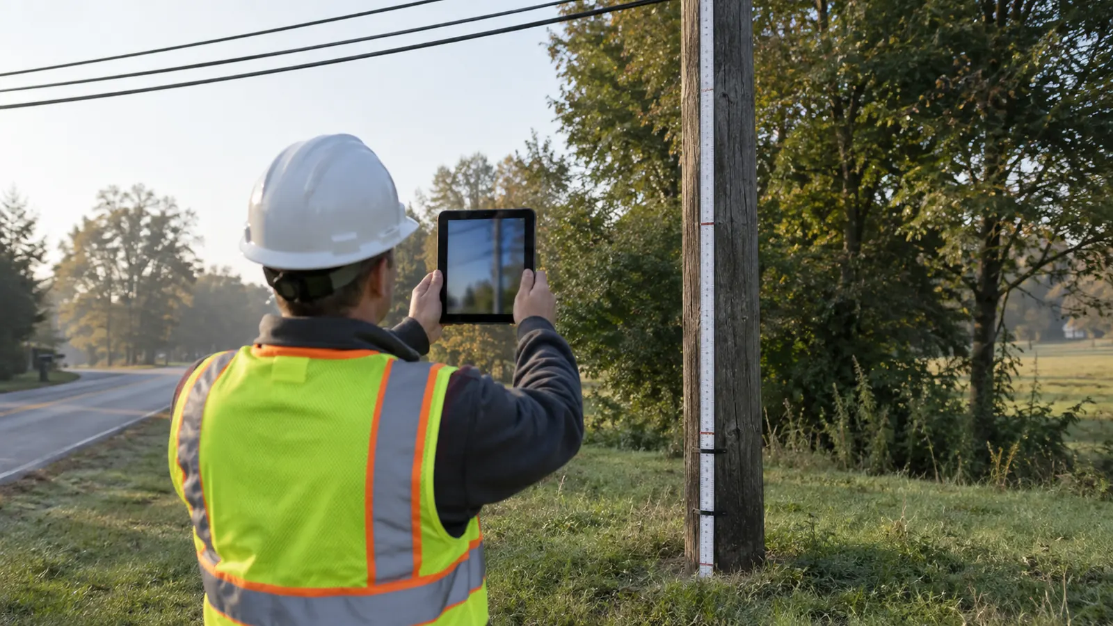
Measurement images differ from overviews. The overview establishes the pole and its surroundings; the calibrated view must support the height measurements the analyst will take from it. We retain the original image and the calibration information together. Cropping or resizing a working copy without preserving its source makes a disputed measurement harder to reproduce, even when the edited picture looks clearer on a report.
Osmose's Use of Range Poles in DMT Process, published July 3, 2018, explains that its Digital Measurement Technology can use a range survey pole placed against the utility pole, with the selected target type matching the photographed target. It also warns that skipping obscured calibration points decreases accuracy. We therefore check target visibility before leaving the location and reject a measurement view whose calibration cannot be defended.
Check the target before departure. Open the actual image at usable magnification while the collector can still retake it. A thumbnail can hide the blur that makes a calibration mark unusable.
Supporting photographs must resolve remaining questions. We need enough detail to read the pole identification and follow an obscured attachment, without treating a close-up as proof of the whole arrangement. A separate view of the anchor can establish its relationship to the pole when vegetation blocks the main photograph. Choose images for the ambiguity they resolve, rather than meeting an arbitrary photo count.
Measurement standards belong in the work order
There is no single accuracy promise we can assign to every camera or collection method. The work order should state the receiving owner's tolerance and the acceptance check appropriate to the instrument. We require units and the measurement method to remain attached to each reported value. Decimal places describe how a number is stored; they do not establish how closely it matches the physical attachment.
Collection must also respect access limits. We plan safe observation positions and use personnel qualified for the work being performed; a missing measurement is a reason to arrange an authorized follow-up, never a reason to approach energized equipment for a better picture. Our field survey data management guide covers the record controls that keep replacement observations connected to the original survey instead of becoming an unexplained overwrite.
O-Calc Pro field data collection QA before modeling
Review the record against its photographs before reviewing a model result. We reconcile the attachment inventory and check that each span points to the intended neighbor. A cable visible in the evidence but absent from the form requires a disposition. The reviewer should not need to know the collector personally to decide whether the survey supports the proposed input.
Resolve exceptions without erasing their history
Assign every exception. Define its release condition. We distinguish a correction supported by an existing image from a revisit needed to obtain new evidence. If engineering accepts an assumption, keep its basis and approver beside the modeled value. That record lets a later designer replace the assumption when better information arrives, without mistaking it for a measurement made during the original field visit.
A small pilot import is useful. We compare the imported record against the capture form, paying particular attention to unit conversion and how directions are interpreted. An accepted file format can still map a height to the wrong component. Once the mapping is confirmed, retain that configuration with the project so a later export does not quietly change the meaning of the fields.
The release check ends with a clear boundary between survey acceptance and engineering approval. We can accept that an attachment height was captured correctly while still withholding approval of the resulting loading analysis. Loading criteria remain the analyst's responsibility. So do model assumptions. A complete field record makes that responsibility easier to exercise; it does not transfer it to the camera or collection application.
Choose the handoff that fits your responsibility
For the field lead: test the capture form on a representative pole before full deployment, and resolve the difficult viewing conditions while the crew can still change its method. Your release decision is whether another person can reconstruct the observed arrangement. Do not close inaccessible measurements as complete simply to clear the day's collection queue.
For the utility engineer: settle the acceptable evidence for uncertain pole properties before assigning production models. Require an explicit disposition for assumptions affecting capacity, especially where an anchor's buried configuration is unknown. Your review should establish whether the evidence supports the design decision, rather than whether every field contains a value.
For the ISP project manager: schedule field-exception resolution as a named handoff before the modeling release. We keep Draftech engineering 100% in-house, and our engineering and turnkey services can carry unresolved survey questions into coordinated make-ready delivery. Construction is full turnkey, delivered by Draftech-managed subcontract crews under our QA/QC and safety program. Active in 24 states. Available across all 50 U.S. states. Send the receiving utility's field requirements to info@draftech.com so we can define that handoff.
If your route needs an engineering package that carries the field evidence through permitting, review our qualifying-route design offer. Draftech engineers the first 20,000 linear feet of a qualifying route at no cost, from feasibility and field survey through permit approval; the owner reviews each request before Draftech commits the package.
Talk with Draftech about your pole-survey handoff. Bring the utility's required fields so we can identify what the collection package must support.