- What Intercity Fiber Engineering Controls in 2026
- Screen Corridor Alternatives Before Route Selection
- Turn the Corridor into a Controlled Route Model
- Coordinate Crossings, Permits and Construction Interfaces
- Release Intercity Fiber Engineering and Verify the Record
- Choose the Intercity Fiber Engineering Release Model We Recommend
An intercity corridor can appear direct on a map while hiding the decisions that govern whether it can be permitted; built; tested; repaired; and operated. A route line alone does not show who controls the roadway edge or where a railroad agreement changes the construction method. It also does not prove that two proposed paths are physically diverse.
This guide treats the corridor as an engineering control system rather than a colored alignment. It complements our long haul fiber engineering definition by focusing on the gated work between an initial corridor screen and a construction release. We explain what each gate should prove without inventing a national permit sequence or a universal design threshold.
What Intercity Fiber Engineering Controls in 2026
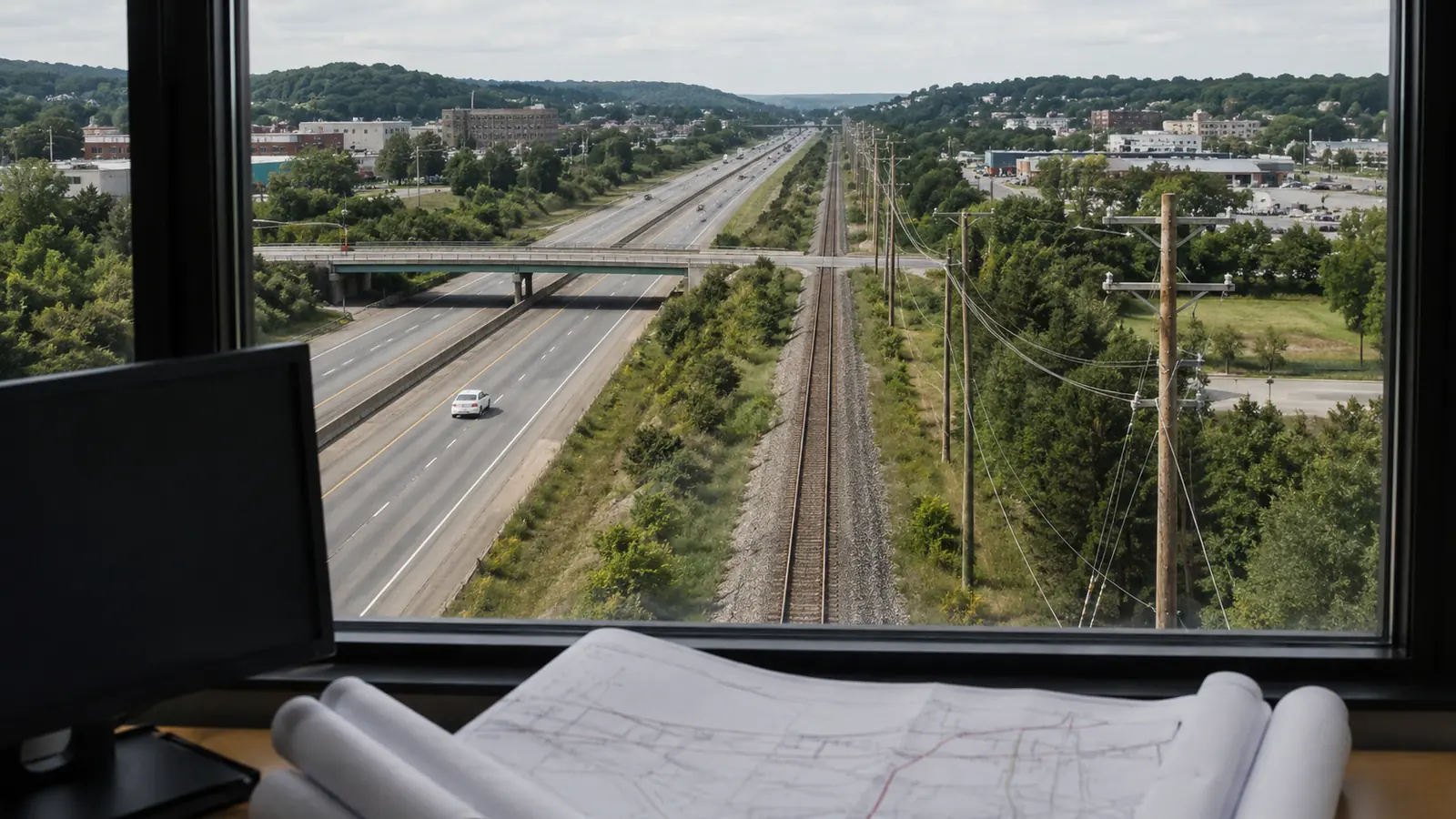
Intercity fiber engineering converts a multi-jurisdiction corridor into a controlled route; crossing plan; optical model; permit basis; field package; and record system; a dependable process uses at least 4 release gates: corridor selection; route definition; construction authorization; and accepted turnover. Each gate proves a different decision without assuming that one approval releases the entire route.
The first control is the decision basis; we state the end points; required handoffs; capacity basis; restoration objective; diversity intent; target service date; and owner constraints before comparing alignments. We also mark which values are contractual inputs and which remain engineering assumptions. If the business case changes then the corridor comparison must change with it. A route selected for the wrong objective is not rescued by detailed drafting.
The second control is geographic scope; an intercity route can move through municipal streets; county roads; state highway ROW; private property; railroad property; waterways; or federal land. Those are possible interfaces rather than a mandatory list. We build an authority register from the actual alignment and preserve each source rule by jurisdiction. The register never treats one agency manual as a national template.
The Federal Highway Administration Utilities Program explains that states decide whether utilities may occupy highway ROW and under what conditions through utility accommodation policies; that statement is useful because it blocks a common shortcut. We cannot assume a highway shoulder is available merely because another state allowed a similar longitudinal installation. We screen the current state policy and then confirm the applicable district process.
The third control is technical continuity; we model cable segments; splice points; structures; slack; entry facilities; powered sites when applicable; and test boundaries as one connected system. The Fiber Optic Association outside plant design guide connects route planning with component choice; link loss analysis; documentation; installation planning; and restoration planning. We use that sequence as technical guidance rather than a permit rule.
The fourth control is decision authority. A route engineer can recommend an alignment and prepare a package. A public agency or property owner decides whether to grant access under its own process. A project release reviewer decides whether the issued documents support the planned work. We keep those decisions separate because an engineering recommendation is not property consent and an issued permit is not automatically a construction work order. Ownership must remain explicit.
Screen Corridor Alternatives Before Route Selection
Corridor screening begins with alternatives that are meaningfully different. We usually compare a roadway-led corridor with at least one separate corridor family when geography permits. Parallel lines on the same bridge or controlled-access segment may fail the stated diversity objective even when their map separation looks large elsewhere. We record shared structures and common access points before assigning any diversity label. Evidence controls release.
Desktop data is evidence for screening rather than proof of field condition. The U.S. Geological Survey National Map offers foundational layers such as elevation; hydrography; boundaries; structures; and transportation. FEMA's National Flood Hazard Layer provides current effective flood hazard data where available. We use both to raise questions for survey and agency review. We do not use either source to certify constructibility or private access. Crossings need context.
Each alternative receives the same comparison fields so a favorable route cannot hide its unresolved items; we describe corridor length as a measured planning value tied to a named GIS revision. We then count identified authority interfaces; major crossings; known property gaps; shared-risk segments; likely construction methods; and data-confidence gaps. A blank is not scored as zero. It remains an open assumption with an owner. Exceptions stay visible.
| Decision gate | Record to compare | Question it must answer | Release result |
|---|---|---|---|
| Need basis | Endpoint and handoff brief | What network outcome governs the route? | Alternatives authorized |
| Corridor screen | Comparable GIS alternatives | Which corridor has the supportable risk profile? | Preferred corridor |
| Route definition | Survey-backed alignment and crossing register | Can every segment enter detailed design? | Design basis released |
| Permit basis | Authority matrix and controlled packages | What external decisions govern each segment? | Eligible scope identified |
| Construction package | Issued documents and current drawings | What work is internally authorized now? | Segment release |
| Turnover | Tests and reconciled records | What installed system has been accepted? | Operational record |
These labels are Draftech project controls and not agency status terms. A state DOT may use different application stages. A railroad may structure access around its own agreement. A county may combine reviews that another county separates. We retain the source wording in the authority register and translate only the internal effect. That makes the matrix reusable without falsely claiming every corridor follows one external process. Operations needs traceability.
The preferred corridor is a decision to investigate further. It is not the final alignment. We preserve rejected alternatives with their assumptions because a denied access request or new field constraint may reopen the comparison. Version history also keeps management from asking why the shortest line was not selected months after the team documented an unavailable crossing or unacceptable shared-risk segment.
Turn the Corridor into a Controlled Route Model
Route definition divides the corridor into segments that can be surveyed; designed; permitted; released; and recorded without losing network continuity; we assign stable segment IDs before sheet numbers exist. Those IDs connect GIS geometry to field observations and crossing details. They also survive drawing reorganization. When one segment changes then the impact review can identify affected permits; splice plans; calculations; and construction packages without renaming the full route.
Survey scope follows uncertainty. Aerial conditions may require pole inventory and attachment inputs. Underground concepts may require visible utility evidence; surface features; structure observations; and selected subsurface investigation under the project scope. Water crossings can require terrain information and owner criteria. We never claim a desktop line has a verified installation method. We attach the observation date and source to every condition that drives design.
The route model must carry uncertainty openly. We use states such as desktop candidate; field observed; authority reference confirmed; owner input pending; and design released. These are internal controls. They do not replace professional judgment or a required sealed deliverable. If one field cannot be verified then we flag it on the segment. We do not let a complete neighboring segment lend false confidence to it.
Crossing registers deserve their own geometry and identifiers; a highway bore; railroad crossing; bridge attachment; water crossing; and private access transition can each control a larger segment. The register stores the controlling owner; location reference; proposed method; profile status; investigation need; drawing reference; application reference; and current disposition. We keep required values project-specific because geometry and owner criteria change by location.
Optical design begins before final quantities. We build a segment loss model from the selected fiber specification; wavelength; manufacturer attenuation; planned splice count; connector interfaces; passive devices; and an agreed engineering margin. The Fiber Optic Association describes insertion loss as including fiber attenuation with connector and splice loss. We calculate with project inputs rather than publishing one loss allowance as a universal answer.
The optical model and physical route must share boundaries. A splice moved across a jurisdiction line changes more than a diagram. It can alter access; enclosure location; restoration strategy; test section length; and construction sequence. We reconcile the route schedule with the splice plan before releasing drawings. For data center endpoints we also coordinate the demarcation and pathway assumptions described in our data center fiber design guide.
Coordinate Crossings, Permits and Construction Interfaces
Permit planning starts from the route model instead of a generic checklist. The 2025 NTIA presentation Preparing for Permitting to Accelerate Broadband Deployment describes local broadband permitting as jurisdiction-specific and encourages communication about the permits and processes required in that area. We turn that caution into an authority matrix. Each row names the governed segment; package basis; application owner; dependency; evidence location; and next internal action.
Railroad interfaces require a distinct owner review; federal Railroad Administration guidance also warns that agency guidance does not bind the public unless authorized by law or incorporated into a contract. We therefore read the current railroad requirements and agreement for the named crossing. We do not turn one railroad's bore detail or insurance language into a universal rule. The project record carries the source edition and review date.
Highway crossings and longitudinal occupancy also stay jurisdictional. Title 23 CFR Part 645 addresses utility accommodation for covered Federal-aid highway contexts. State policies and permits supply the location-specific criteria. We map the route stationing to the permit limits and drawing revision. If the alignment leaves those limits then the affected segment returns to review. We do not treat nearby permitted work as transferable authority.
Construction method is coordinated with access and permit basis. Plow; trench; directional bore; aerial placement; bridge attachment; or existing conduit may be evaluated where appropriate. The engineer selects and documents the proposed method using available information and owner criteria. The construction subcontractor later confirms means and methods within its scope. Any proposed deviation returns through the controlled review path before affected work proceeds.
Self-critical note: our corridor matrix can make weak source data look orderly. We counter that weakness by exposing confidence; review date; and unresolved ownership beside every score. If the evidence is not current enough for a release decision then a polished matrix does not improve it.
Schedule control stays honest when it separates external events from internal actions. We can set dates for survey completion; package checks; response drafting; and follow-up. We cannot manufacture an agency decision date. A forecast may inform sequencing but it remains labeled as a planning assumption. The baseline keeps permitted segments visible while showing where one unresolved crossing interrupts continuity or prevents access to later work.
For nationwide planning we use the Draftech service-area index only as a starting point for staffing and local research; every corridor still receives its own jurisdiction check. State availability does not mean identical rules. County procedures can differ inside one state and owner agreements can add controls beyond public permits. The route matrix should reveal those differences rather than flatten them.
Release Intercity Fiber Engineering and Verify the Record
A design issue and a construction release answer different questions. The design issue identifies the engineered package and its maturity. The construction release confirms that a defined segment may proceed using the current package with the necessary external decisions and internal conditions. We require one named release authority on the project team. We also keep held geometry visible so a subcontractor cannot infer permission from an adjacent released segment.
Before release we compare the issued permit or property agreement with the current alignment; method; sheet revision; work limits; stated conditions; and access plan. We check open comments and dependent crossings. We also verify that the field package points to the same cable schedule and splice plan used by the optical model. A mismatch produces a hold or a documented disposition. It never disappears inside a meeting note.
Draftech develops engineering in-house. Physical construction is performed by subcontractors. We manage and oversee that construction against the released engineering; permit conditions; safety roles; quality plan; and change process defined for the engagement. We do not portray subcontracted crews as in-house construction staff. We also do not take the authority of an owner; agency; engineer of record; or contractor role that the project has assigned elsewhere.
Field change control protects both engineering intent and authority limits. The subcontractor records the location and reason for a proposed deviation. We review the route effect; crossing effect; optical effect; permit effect; and record impact with the appropriate project parties. Urgency does not turn an undocumented relocation into accepted design. The approved disposition identifies the changed geometry and the drawings or permits that require revision.
Testing is tied to design sections and acceptance criteria. We define the required inspection records; continuity checks; insertion-loss tests; OTDR traces when specified; fiber identification; and exception disposition in the project documents. The Fiber Optic Association testing guidance distinguishes measured insertion loss from event-location information. We avoid treating one test method as a substitute for the other or inventing a pass threshold not supplied by design.
Turnover reconciles the physical and optical records. We compare installed route geometry with segment IDs; closure locations; cable and fiber assignments; permit limits; field changes; test files; and unresolved exceptions. Each record carries a revision and acceptance state. The dark fiber route engineering guide addresses the operating and commercial controls that follow. This guide stops at an accepted engineering record and controlled handoff.
Choose the Intercity Fiber Engineering Release Model We Recommend
Carrier planning a new corridor: choose a staged alternatives model with a written need basis and at least 2 meaningfully different corridor families when geography permits. Release the preferred corridor only after shared-risk segments and authority interfaces are visible. We recommend preserving the rejected alternatives because one access decision can reopen the comparison before detailed design.
Data center team buying route diversity: choose a common-risk model that traces each path through bridges; railroad property; highway segments; entrances; meet-me locations; and controlled facilities. We recommend requiring evidence for claimed separation. Two carrier diagrams are not enough when both paths use the same structure or when the available records cannot establish physical independence.
Owner preparing a construction release: choose a segment register that joins current drawings to external decisions and subcontractor work packages. We recommend separate states for design issued; permit evidence verified; internally released; held; installed; tested; and accepted. The map should show held limits with the same prominence as released limits so schedule pressure cannot erase a boundary.
Our ISP and carrier network engineering approach keeps corridor engineering in-house while construction remains subcontracted and is only managed or overseen by Draftech. The Draftech delivery model explains our company structure. Those links provide context rather than changing the rule in this guide: release authority and construction responsibility must be named by the engagement.
If your corridor alternatives no longer match the route model or the released package no longer matches field intent then email info@draftech.com. We can review the control structure and identify where the evidence chain breaks. The useful output is not a sales promise. It is a precise list of route decisions that need new evidence or disposition.
A sound release lets every party answer the same question from the same revision. We know which geometry is engineered; which access decisions are external; which work package the subcontractor holds; which tests map to each section; and which records have been accepted. That alignment is the practical result of intercity fiber engineering. It keeps a long corridor from becoming a chain of unrelated drawings.
Talk with Draftech about an intercity corridor release review. Bring the need basis; route alternatives; segment register; crossing matrix; authority records; current drawings; optical model; subcontractor packages; test plan; and turnover index so we can begin with the evidence already under control.