Types of fiber splicing: understand the joining methods
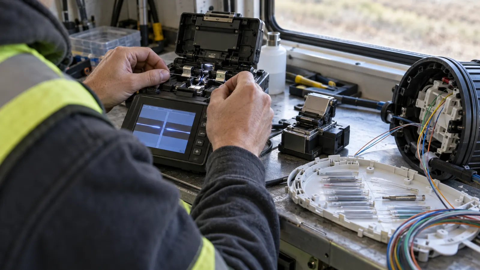
The types of fiber splicing used in network construction fall into 2 joining mechanisms: fusion and mechanical. Single-fiber fusion joins individual fibers with an electric arc; ribbon mass fusion joins a prepared group in one operation. Mechanical splicing holds aligned fiber ends together inside a dedicated component without melting the glass.
We choose the method around the connection being built. A drop serving an individual premise presents a different handling problem from a feeder cable carrying many circuits through a closure. Cable construction matters too. A high fiber count alone does not establish whether the crew can splice the cable as ribbons.
The Fiber Optic Association's Reference Guide to Fiber Optics, in its pages on Fusion Splicing and Mechanical Splices, describes these mechanisms and the preparation they require. Its ribbon discussion gives a 12-fiber ribbon as a common example of mass fusion. That is a useful illustration, not a universal ribbon size or a production-rate promise.
Start with the splice schedule
We start our review with the proposed fiber connections. The schedule should identify which fibers continue through the location and which branch toward a terminal or another cable. A count of cable ends leaves too much unresolved. The crew needs the actual pairing before opening a tube or separating a ribbon.
Consider a planning example, rather than a project result: a feeder passes through a closure while a small branch leaves toward customers. The continuing groups may suit mass fusion, but the branch can require individual access. We would resolve that transition in the splice design before selecting tray hardware, because the way fibers leave the group affects how they can be stored.
Service status changes the work. A new cable can be prepared without disturbing an operating circuit, while a repair inside an occupied closure requires positive identification of affected fibers and an authorized outage plan. We keep that distinction visible in the work package. The method choice never grants permission to cut a fiber that happens to be accessible.
Match the hardware before mobilization
The closure and its tray system have to accept the selected splice protection. A holder intended for individual sleeves may not retain a ribbon protector, and a mechanical splice body may require a different insert. We check the approved component combination rather than assuming that unused tray space makes the substitution workable.
Cable dimensions need the same attention. The entry seal must suit the cable jacket, and the internal routing must suit the buffer tubes or ribbon structure actually supplied. If the delivered cable differs from the drawing, we resolve the discrepancy while there is still time to change the materials. The splicer should not inherit an improvised storage arrangement.
Our recommendation is to qualify the complete assembly, including how a technician will reopen it. Equipment compatibility alone leaves that question unanswered. A technically possible splice can still create a maintenance problem if the next technician must lift active fibers to reach the intended branch.
Compare the methods against the cable and work scope
A useful comparison starts with the task. We separate the joining operation from the handling that surrounds it, because a faster arc cycle cannot remove the time required to identify a live fiber or dress slack into a crowded closure.
The table compares practical choices without assigning a universal splice-loss figure. Acceptance limits belong in the approved test requirements. For that part of the decision, use our OTDR testing acceptance criteria and fiber splice-loss guide and confirm the applicable limits with the network owner before work starts.
| Decision | Single-fiber fusion | Mechanical | Ribbon mass fusion |
|---|---|---|---|
| Joining operation | Arc joins individual glass ends | Fixture retains aligned ends | Arc joins a prepared fiber group |
| Drop connections | Individual connections and selective access | Only where the owner approves the application | Evaluate only where grouped work fits |
| Feeder cable | Loose fibers or selective branches | Specified repair or exception | Compatible groups continuing together |
| High-count work | More individual handling | Confirm component and application approval | Evaluate group preparation and branch pattern |
| Tray requirement | Compatible individual protectors | Holder suited to splice body | Compatible ribbon protectors and routing |
Single-fiber fusion for individual connections
Single-fiber fusion melts aligned glass ends together with an electric arc. The technician removes the coating over the required length and cleans the exposed glass before precision cleaving. The prepared ends go into the splicer under the procedure for that equipment and fiber combination. After the joint is made, compatible protection supports the exposed splice.
We favor this approach for individual drop connections and selective branching where fibers must be handled separately. It also works on feeder cables built with loose fibers. The deciding question is how many individual connections the approved splice schedule requires, rather than whether the word feeder appears on the drawing.
Single-fiber work keeps each pairing accessible during assembly. That can help when a cable transition or repair needs close attention to particular fibers, but the advantage depends on disciplined identification. A correctly formed joint between the wrong fibers still leaves the network connected incorrectly. We want the schedule beside the work, not reconstructed from memory afterward.
Our preference has a limitation. Choosing individual fusion by habit can make a high-count, straight-through ribbon job unnecessarily laborious, particularly when the design already preserves ribbon groups from cable entry through the tray. We review the handling sequence before specifying individual splices across the entire cable. Familiar equipment should not decide the architecture.
Mechanical splicing for approved limited applications
A mechanical splice retains prepared fiber ends in an alignment fixture, commonly with an index-matching material at the interface. The glass remains separate. Preparation still requires controlled stripping and a suitable cleave; omitting the fusion arc does not remove the need for clean, accurately prepared ends.
We consider mechanical splicing where the owner has approved the component and the application, including a limited repair or a particular drop arrangement. The Fiber Optic Association's Mechanical Splices reference describes temporary restoration and permanent joining applications. Calling every mechanical splice temporary would therefore be inaccurate. Its allowed role belongs in the network's construction requirements.
The practical appeal is the ability to make the joint without a fusion machine. That advantage has boundaries. The component must match the fibers and fit its holder, and the technician must follow its assembly procedure. We would not replace a specified fusion joint simply because a mechanical component is available in the vehicle.
Restoration needs a recorded disposition. If the repair is temporary, we recommend assigning responsibility for the permanent work before the crew leaves, with the affected fiber identified in the restoration record. If the owner accepts it permanently, the installed method and component still belong in the as-built documentation. Later crews should be able to tell what they will encounter.
Ribbon mass fusion for compatible grouped fibers
Mass fusion processes a prepared ribbon group together using ribbon-capable tooling and holders. The matching groups are stripped and cleaved as assemblies before fusion, with a compatible protector supporting the finished group. The Fiber Optic Association's ribbon-splicing tutorial shows the group held through those preparation operations, preserving its arrangement for the splice.
High-count feeder cables are a natural place to evaluate this method. We look for runs where groups continue together and the cable format supports the planned preparation. A ribbon cable that repeatedly breaks into small branches needs a different handling plan from a straight-through feeder, even when both carry the same total number of fibers.
Loose fibers can sometimes be organized into ribbons using compatible procedures and tooling. That conversion is additional work. We require the proposed approach to account for fiber order and the transition into storage, rather than treating loose-tube cable and factory ribbon as interchangeable inputs. The selected equipment documentation must support the actual fiber format.
Group handling changes rework. Before authorizing production, we want the contractor to explain how a defective connection within a ribbon will be accessed and corrected under the applicable procedure. A group operation does not remove individual fiber identity. The test records must remain traceable to every circuit represented in that group.
Splice trays and closures make the method maintainable
The tray organizes protected joints and stored fiber inside the enclosure. The closure provides the cable-entry and environmental protection around that assembly. Both matter. A splice protector should sit securely in its designated holder while the fiber follows the tray's routing features without tension or an unapproved bend.
We review capacity against the installed configuration. A closure's advertised maximum may depend on a particular tray arrangement or protector type, so we verify the configuration being purchased against the planned connections and reserved space. Adding a tray later can also depend on the available cable-entry and storage arrangement.
Separate stored fiber from mechanical loads
Cable retention should carry the load intended for the cable attachment, following the closure procedure. Bare fiber must not become the restraint for a moving cable. We also check how buffer tubes enter the tray, especially where tray movement could pull on a tube or transfer tension into stored fibers.
The enclosure location shapes maintenance access. A closure that fits inside a vault may still be awkward to lift to a working position once the cables are installed. Our fiber cable enclosure placement guide addresses that placement problem. We resolve working access and slack storage together before treating the location as ready for construction.
Before sealing: Ask the installer to demonstrate that the designated tray can be accessed with the fibers routed as installed. Resolve interference while the closure is open, rather than discovering it during a later service visit.
Reentry deserves its own review. We want the labels to remain readable after trays are stacked, and we check whether the designated branch can be reached without lifting unrelated stored fiber out of its routing features. A photograph should show that arrangement clearly enough for the inspector to compare it with the approved closure detail.
Environmental sealing follows the supplied closure instructions. The installer needs the correct preparation at each cable entry and the required verification for that enclosure. We keep these tasks visible in the inspection scope because an accepted splice operation leaves the closure assembly unfinished until its retention and sealing work are complete.
Control identification, testing, and field changes
Fiber identity begins before splicing and continues into the test file. We want the cable designation and fiber assignment to agree with the splice schedule at the work location. Color is useful for locating a fiber within a known cable structure; it cannot establish which route that cable serves.
For a color lookup during that identification work, the Fiber Color Code Chart is a free fiber color code chart (ANSI/TIA-598) that maps a fiber number to its buffer tube and fiber colors. Use it with the cable's own identification information and the approved schedule. Repeated colors still require the correct tube or group reference.
Testing stays tied to individual fibers. We require the specified test records for the installed connections, including fibers joined as a ribbon group. A production count showing completed ribbon operations cannot establish that every assigned circuit reaches its intended destination. The submitted records need enough identification to reconcile the test result with the installed connection.
Our OSP construction inspection checklist explains how to put inspection points into the work sequence. For splicing, we recommend agreeing on the evidence needed before the closure is sealed. Photographs can document routing and labels, while the required optical tests address the completed fiber path.
Resolve substitutions before they disappear into the tray
Field substitutions can affect maintenance even when the crew can physically assemble them. A different protector might need another tray insert, or a changed cable format might require individual handling where the schedule assumed ribbons. We require the design consequence to be resolved before the replacement becomes the installed condition.
The fiber construction RFI workflow provides a way to raise that discrepancy and obtain a recorded answer. The request should identify the proposed change clearly enough for the responsible engineer to evaluate the actual connection. A vague request to use an equivalent leaves the installer guessing about what was approved.
That coordination is part of our fiber construction management scope: the approved splice arrangement must agree with the materials and the acceptance work. Draftech's engineering is 100% in-house. We deliver full turnkey construction through Draftech-managed subcontract crews, with responsibility for field execution distinguished from engineering review.
Record the installed arrangement: When an approved change moves a connection to another tray, update its location in the splice record before closeout. A correct fiber assignment becomes harder to maintain when its recorded tray location is wrong.
Choose types of fiber splicing by the work you must deliver
Drop deployment teams: Use single-fiber fusion for individual connections where that is the approved network method. Keep mechanical splicing for applications the owner specifically accepts. Confirm the terminal or closure arrangement before mobilization so the assigned technician has a supported place to protect and store the joint.
Feeder construction managers: Select mass fusion where compatible ribbon groups continue through the splice location. Require a preparation and storage plan for transitions into individually handled fibers. The benefit comes from preserving useful groups through the work, so include the branch pattern when reviewing the contractor's proposed method.
Maintenance and restoration teams: Choose the approved repair method around the affected circuits and available access. Establish the outage authority before cutting. Record whether the installed repair is permanent, and leave a clear work requirement for any temporary connection that still needs replacement.
Network owners: Specify the permitted methods and the acceptance requirements before bid comparisons. Ask bidders to explain how their proposed closure configuration supports future access. We recommend rejecting a method substitution that lacks a compatible tray arrangement, even if the contractor expects the joining operation itself to be straightforward.
We bring the fiber assignments and closure details into the same engineering review so managed crews can work from a buildable package. That resolves the mismatches discussed here before an inspector is asked to accept concealed work. Active in 24 states. Available across all 50 U.S. states.
For a route still entering design, our free engineering offer can establish that package early: Draftech engineers the first 20,000 linear feet of a qualifying route at no cost, from feasibility and field survey through permit approval. The owner reviews each request before Draftech commits the package.
Discuss your splice package with info@draftech.com.