- Why Small Cells Trigger Pole Loading Review
- Inputs Required Before the Calculation
- Small Cell Pole Loading Requirements: Outcomes at a Glance
- NESC Load Cases That Set Small Cell Pole Loading Requirements
- FCC Timelines That Shape Small Cell Pole Review
- Common Reasons a Small Cell Fails
- Make-Ready Outcomes and Permit Package Needs
- How to Keep the Review Moving
- What This Means for Your Node List
Small cell pole loading requirements get underestimated because the equipment looks small. A radio that weighs 47 pounds does not scare anyone in a conference room. Put that same radio, antenna bracket, fiber enclosure, power disconnect, and riser at 27 feet on a pole that already carries electric and communications attachments, and the calculation can change fast.
The question is not whether the radio is heavy. The question is how the total attachment changes bending moment, transverse load, vertical loading, clearance, and safety factor under the controlling NESC condition. Pole loading needs to run early enough to shape the design, not late enough to become a rejection letter.
Why Small Cells Trigger Pole Loading Review
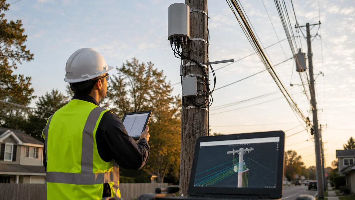
Small cell pole loading requirements are the structural and clearance checks required under NESC Rule 250 wind, ice, and combined loading cases before a pole can carry 5G radio and fiber attachments. A radio and bracket assembly mounted at 27 feet adds bending moment and wind area that an already-loaded pole may not have margin to absorb.
A small cell attachment can include more than a radio. The pole may receive an antenna shroud, radio head, power supply, disconnect, fiber junction, conduit riser, mounting arms, grounding conductor, and sometimes a cabinet or meter equipment nearby. Each piece has weight, exposed area, attachment height, and separation from existing facilities.
On a wood utility pole, the added wind area often matters more than the dead weight. Move the attachment higher and the same piece of equipment can create a larger moment at groundline. Add ice loading, existing secondary conductors, a slack span, and telecom cables, and the margin can disappear.
That is why small cell pole loading requirements belong in the same planning lane as small cell design engineering, not as a final stamp after the node layout is already drawn.
Inputs Required Before the Calculation
A useful pole loading model is only as good as the field data and equipment data feeding it. Missing attachment heights or guessed equipment dimensions can produce a pass that later fails when the utility reviews the package.
At minimum, the engineer needs:
- Pole data: class, species or material, height, birthmark data, and visible condition notes.
- Attachment heights: measured heights for electric, communications, guys, streetlight arms, and proposed small cell equipment.
- Span geometry: span lengths, wire sizes, cable types, and direction of pull for existing attachments.
- Equipment cut sheets: weight, dimensions, effective projected area, mounting bracket data, and required clearances.
- Loading assumptions: local wind, ice, and loading district requirements from the pole owner or jurisdiction.
None of those inputs are safe to estimate. A pole loading model is a physics calculation, not a checklist, and it is only as reliable as the weakest input feeding it. An assumed span length that is off by 15 feet changes the load on every attachment on that pole, not just the proposed one, and an equipment cut sheet the RF vendor has not finalized is a placeholder, not a data point.
Photos matter too. A field sheet may say the pole is clear. The photo may show a riser conflict, a transformer lead, a damaged guy marker, or a communications bundle that was measured as one cable but behaves like three.
If the equipment cut sheet is not final, label the pole loading as preliminary. Do not hide that assumption. A 9-inch change in radio depth can matter under wind loading.
Small Cell Pole Loading Requirements: Outcomes at a Glance
Every small cell pole loading review lands in one of five outcomes, each carrying a different schedule impact. The sections that follow walk through why a pole ends up in each one and what fixes it.
| Outcome | What It Usually Means | Schedule Impact |
|---|---|---|
| Pass as proposed | Proceed with permit drawings, owner application, and construction package | None |
| Pass with rearrangement | Move existing communications, adjust attachment height, or add cleaner separation | Adds a design cycle, usually no field delay |
| Pass with guying or reinforcement | Add guy, brace, or approved reinforcement if the pole owner allows it | Adds an owner approval step before construction |
| Fail, replacement required | Replace the pole or select another node location | Longest delay; adds pole procurement and a separate construction visit |
| Insufficient data | Field revisit, equipment confirmation, or owner data request before submission | Delays submission until the missing data is resolved |
Read the schedule impact column before committing to a node's timeline. A pass with rearrangement is not the same commitment as a pass with guying.
NESC Load Cases That Set Small Cell Pole Loading Requirements
Most utility pole reviews are built around National Electrical Safety Code criteria plus owner-specific rules. The exact cases vary by region and pole owner, but the calculation usually checks wind, ice, combined loading, vertical load, guying, and clearance impacts.
NESC Rule 250B sets the strength requirements for Grade B and Grade C construction, and Rule 250C defines heavy, medium, and light loading districts, each pairing a wind pressure and ice thickness assumption the pole owner's standard specifies for the project. A small cell attachment analyzed under a heavy district can fail at a bracket offset that would pass under a light district, which is why that assumption belongs in the pole owner's standard, not in the design software's default.
For small cells, the sensitive inputs are usually attachment height, equipment projected area, mounting offset, and the relationship to existing electric supply space. A compact side-mounted radio can be easier to place than a larger shroud, but if the bracket pushes equipment away from the pole face, the moment arm changes.
The software matters less than the assumptions, but the model still needs to be clean. In O-Calc Pro pole loading analysis, small cell equipment has to be represented with the right dimensions and loading direction. In SPIDAcalc, the same issue appears in how equipment and brackets are modeled against span directions. The comparison article on O-Calc Pro vs. SPIDAcalc covers those workflow differences.
Clearance is a separate check. A proposed fiber riser or disconnect might pass structural loading and still fail because it enters supply space, blocks climbing space, or conflicts with a streetlight handhole.
For small cell work, we also separate structural questions from attachment-administration questions. A pole can pass the calculation and still need owner approval for climbing space, equipment orientation, disconnect location, or fiber riser protection. That distinction matters because the fix is different. Engineering can solve a loading issue with a lower attachment or added guying. Only the owner can approve a nonstandard mounting detail.
Another detail that gets missed: proposed equipment is not the only new load. The riser, messenger transition, grounding conductor, snow shield, cabinet bracket, and slack storage can all add projected area or clearance conflicts. Small numbers add up when they sit high on the pole.
FCC Timelines That Shape Small Cell Pole Review
The pole loading calculation does not happen in a regulatory vacuum. The FCC's 2018 Small Cell Order set shot clocks of 60 days for a small wireless facility collocated on an existing structure and 90 days for a new structure, and Section 6409(a) of the Spectrum Act adds a separate 60-day clock for eligible facilities modifications that do not substantially change an existing structure's physical dimensions. Those clocks govern the siting application, not the pole owner's structural review, but the two run on the same calendar in practice, so a pole loading fail at week six of a 60-day clock leaves almost no room to redesign, resubmit, and still meet the deadline.
Common Reasons a Small Cell Fails
The first failure mode is simple: the pole was already close to capacity. A small cell attachment is just the last load added to a pole that should have been replaced or guyed years ago.
The second is bad field data. We see this when attachment heights are rounded, span lengths are pulled from GIS without verification, or existing communications cables are not separated correctly. A pole that looks fine in a rough model can fail after the utility field auditor corrects the inputs.
Third, decorative and municipal streetlight poles create their own problems. They may not have a standard wood-pole class. The city may require manufacturer structural data or a PE letter. Sometimes the pole can carry the radio but not the cabinet or power equipment in the proposed configuration.
A fourth pattern shows up on poles that pass the structural check but fail on attachment administration. Climbing space and communication-to-supply space separation do not bend for a small radio just because the bending moment number looks fine, and a pole owner can reject a mounting position on clearance grounds alone even when the structural load clears with room to spare.
Field check worth the extra ten minutes: measure existing attachment heights with a rod or laser, not a tape estimate from the ground. A four-inch error is enough to turn a passing separation check into a failing one once small cell equipment is added above it.
Last, there is the conduit issue nobody wants to own. Many streetlight poles were not designed for telecom risers. If the fiber cannot share the existing power conduit, the design may need a new riser, handhole, or underground stub. That turns a clean-looking attachment into a civil permit.
Make-Ready Outcomes and Permit Package Needs
A pole loading review does not just return pass or fail. It should tell the design team what to do next, drawing from the five outcomes covered earlier.
For permitting, the package should include the pole loading report, field photos, equipment cut sheets, proposed elevation, grounding note, attachment height table, and any owner-specific application form. Reviewers routinely reject packages missing even one item, which restarts the clock rather than pausing it. If make-ready is required, call it out directly. Hiding it in a note creates friction later.
A complete package also states the loading district assumption and the software used to run the model, since some pole owners will not accept a report without both. Leaving that out is a common reason a sound pole loading report comes back with a data request instead of an approval, which is where our pole loading analysis service earns its keep by building the report to the owner's format the first time.
The broader NESC pole loading compliance guide explains how these attachment checks fit into aerial fiber work. Small cells use the same discipline, with more equipment geometry and more jurisdictional review layered on top.
How to Keep the Review Moving
Start the pole loading track during candidate validation. Do not wait until the RF team has defended every location and the permitting team has built a full sheet set. At that point, a failed pole becomes a political problem instead of an engineering adjustment.
We like a three-pass screen. First, field crew captures pole owner, class, visible condition, attachment heights, photos, and access notes. Second, engineering runs a preliminary model with the planned equipment. Third, the design team resolves failures before the permit package is submitted.
When a node fails, ask whether the coverage objective can survive a 60-foot move to a better pole. Sometimes it can. Sometimes it cannot. But that conversation is cheaper before the city review clock starts. It also pairs well with the workflow we cover in small cell 5G fiber backhaul engineering, since a node move usually changes the backhaul route too.
What This Means for Your Node List
Carrier or turf vendor running a multi-market build: Screen pole loading before RF signs off on the candidate, not after. A node that fails structurally after three internal RF reviews costs far more schedule than one flagged during candidate validation.
Municipality, DOT, or pole owner reviewing an applicant's package: Confirm the loading district assumption and software used are both stated, and treat a missing equipment cut sheet as an incomplete application. A pole can pass loading and still need a lower attachment height or added guying, and that sign-off belongs to the owner, not the engineer.
Design firm or ISP building the candidate list: Run the three-pass screen described above before permitting builds a full sheet set. The pole that fails is cheaper to replace on paper than after the crew is standing at the base of it.
Talk to our pole loading team about your small cell candidate list. We'll flag which poles are buildable as proposed and which need redesign before your permit package goes in.
Draftech's OSP and wireless engineering teams handle field survey, route design, pole loading analysis, permit drawings, and utility coordination in-house, so the structural check, the RF constraints, and the permit package get built on one clock instead of three. Construction, when the candidate list moves to build, goes out to Draftech-managed crews under our QA/QC program, so the team that flagged the pole risk stays accountable through the build.
If your small cell candidate list has pole risk hiding in it, send the equipment cuts and node map to info@draftech.com. We'll help separate the buildable poles from the ones that need redesign before the permit clock starts.