Fiber optic cable reel length planning is one of those LLD details that gets treated like an afterthought — right up until a project manager calls asking why the splice count doubled from the estimate. I've seen it happen on FTTH builds in rural Mississippi, on middle-mile routes through the hill country of central Texas, and on suburban deployments where nobody bothered to run the reel math before placing the purchase order. The cable shows up. The reels are the wrong length. Now you're adding closures to a construction package that wasn't budgeted for them.
This isn't abstract. Every reel end is a splice. Every unplanned splice is a closure, a fusion-splicer deployment, a test event, and a labor ticket. On a well-run project, your splice point placement guide drives the reel order — not the other way around. But to do that correctly, you need to understand what the manufacturers actually offer and what the physical constraints look like at various fiber counts.
Standard Reel Lengths by Fiber Count — What's Actually Available
Manufacturers don't publish a single universal reel length. It depends on cable diameter, jacket weight, and reel capacity. Here's how it generally breaks down in practice:
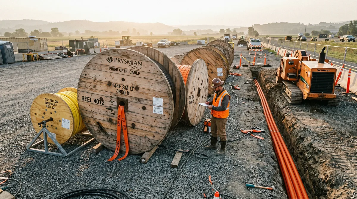
12-fiber through 48-fiber cable — These are your feeder drops and shorter distribution runs. Most manufacturers can spool these at 20,000 feet without breaking a sweat. Corning, OFS, and Prysmian all offer 20,000-foot reels for loose-tube cables in this fiber count range. Some will go to 25,000 feet on request for 12F, though you'll pay a premium for the larger reel and may face delivery logistics headaches if the staging area is tight.
96-fiber through 288-fiber cable — Mid-count distribution cable. The practical maximum here is typically 10,000–15,000 feet. Cable diameter and reel weight start imposing real limits. A standard 288F loose-tube cable on a 15,000-foot reel runs somewhere around 2,200 to 2,600 lbs depending on the jacket type and armor. That's manageable with a cable trailer and a decent capstan, but it's worth flagging in your cable delivery plan. Some contractors have tried to stage 15,000-foot reels on routes where the only access was a shared-use path. That doesn't go well.
432-fiber and above — High-count backbone cable. Here you're typically looking at 6,000–8,000 feet as the practical ceiling, and often lower. A 432F or 864F ribbon cable reel at 8,000 feet can exceed 4,000 lbs. Staging, transport, and placing the reel without a full cable-placing machine becomes a genuine challenge. On a project in central Georgia last year, we had 864F cable ordered at 8,000-foot reels and the contractor's cable roller setup couldn't handle it without skipping a planned figure-8 midspan pull — we ended up with two extra closures that weren't in the original splice design.
Rule of thumb: Always confirm maximum available reel length directly with the manufacturer during the design phase — before the cable order is placed. Standard catalog sheets often list shorter reel lengths as the default. You may need to specifically request longer reels, and lead time can be 8–14 weeks for non-standard lengths.
How Fiber Optic Cable Reel Length Determines Splice Point Locations
This is where the LLD engineer earns their keep. Splice points aren't just a splicing decision — they're a reel-length decision. When you build your fiber construction package deliverables, the cable cut sheet should already account for reel lengths before a single strand is ordered.
The logic is straightforward. Take a distribution route that's 4.2 miles long — about 22,176 feet. If you're using 288F cable and the manufacturer's standard reel is 10,000 feet, you're looking at three reels minimum and two mandatory mid-route splice points. If you can get 15,000-foot reels, you might be able to cover that same route with two reels and one splice, saving a closure location, a fusion splicer setup, and the associated test documentation.
But here's what gets missed: the reel end doesn't have to land at a convenient location. If your cable is running down a county road with no vault access, a reel end forces you to install a splice enclosure somewhere along the route — aerial or buried — at a location determined by math, not engineering logic. The best-placed splice points are at existing structures: hand holes, vaults, FDH locations, aerial lashing points near pole hardware. A bad reel length decision puts a splice in a ditch with no access, 600 feet from the nearest hand hole. That closure becomes a maintenance liability for the life of the network.
This is why segment-by-segment analysis matters. On any route longer than a single reel, sketch out the segment spans and work backwards from your desired splice locations. Then figure out what reel lengths get you there cleanly — or close enough that you can account for the difference with service loop slack.
The Cost Tradeoff: Fewer Splices vs. Cable Waste
Larger reels cost more per foot in some cases, and they almost always leave waste. That's the real tradeoff. If you use a 15,000-foot reel on a 13,200-foot segment, you're wasting 1,800 feet of cable — cut off at the far end, coiled in a vault as service loop, or discarded. At roughly $0.80–$1.40/foot for 144F loose-tube cable (depending on fiber count and market conditions), that 1,800 feet represents $1,440–$2,520 in material.
Compare that to the cost of a fusion splice closure installation. Labor to install a single aerial closure — including lashing, hardware, splicing 144 fibers, testing, and documentation — runs $800–$1,600 depending on your market. Add the closure hardware itself ($150–$400 for a re-enterable enclosure), and you're looking at $950–$2,000 per mid-route splice point.
The math usually favors the longer reel. Not always. On short segments with predictable reel-end placement, shorter reels may leave less waste and the splice cost is acceptable. But on long open routes — rural aerial builds, county road undergrounds — the bias should be toward longer reels every time.
One more factor: reliability. Every fusion splice is a potential failure point over a 20-year network life. Fewer splices means fewer future trouble-ticket locations. That's hard to quantify, but any network operator who's spent a night tracking down a bad splice in an unmarked aerial closure understands the value intuitively.
Midspan Pulls: When the Route Is Longer Than Any Available Reel
Sometimes there's no reel long enough. You've got a 19,000-foot aerial run with no viable intermediate splice location, and your best available reel is 12,000 feet. That's where the midspan pull technique comes in — and it's one of those things that looks simple on paper but has a dozen ways to go wrong in the field.
The concept: position the reel at roughly the midpoint of the route. Pull in both directions — either simultaneously with two crews, or sequentially by pulling one direction, cutting, then repositioning for the return. The advantage is that you cut the maximum pull tension in half compared to pulling from one end. On long aerial routes, that tension difference can be the difference between a clean pull and damaged fiber.
The execution requires figure-8 laying the slack on the ground. When pulling from the midpoint, the cable comes off the reel and the slack accumulates on the ground as a figure-8 pattern — this prevents rotation and kinking that a simple pile would cause. That figure-8 then feeds out cleanly as the pull progresses in the opposite direction. Sounds straightforward. But if the figure-8 is laid on uneven terrain, or someone drives across it before the second pull, you've got a problem.
Terrain matters enormously here. On a flat open field in the Delta region of Mississippi, a midspan pull is clean. On a route with significant elevation changes — anything over about 4% grade — the pull tensions become asymmetric and the figure-8 staging gets complicated. Intermediate pull points may be necessary. I've seen routes through hill country where the original plan called for a midspan pull, and the field crew ended up adding two mid-route closures because the terrain made the figure-8 staging impractical. That wasn't in the budget.
Matching Reel Lengths to Route Terrain and Construction Sequence
The terrain analysis for reel selection isn't just about pull tension — it's about where you can physically stage a reel. A 15,000-foot reel of 288F cable weighs over two thousand pounds and requires a cable reel trailer or a properly rigged capstan setup with roller stands. You can't stage that next to a guardrail on a mountain switchback.
On a project outside Billings, MT a few years back, we had an aerial route following a county highway through rolling terrain. The original cable order specified 12,000-foot reels of 144F cable. The field crew got out there and found that the only viable staging locations for a reel that size were at the two route endpoints — because every intermediate access point had either a steep bank, overhead obstructions, or a drainage ditch on the shoulder. What should have been a two-pull route with a midspan setup turned into three separate pulls using shorter reels, adding two splice points that weren't in the original LLD. The construction cost on that section went up about 18% from the original estimate.
The lesson: reel staging locations need to be identified during the LLD phase, not after the cable ships. Your aerial vs underground construction cost analysis should flag terrain constraints that affect reel selection, not just material differences between installation methods. When you know a route has limited staging access, that drives you toward shorter reels or a midspan pull plan documented before construction starts.
Construction sequence also matters. Cable reels tie up the delivery schedule in ways that other materials don't. — our fiber construction BOM guide covers the full material list If you have a 14-week lead time on 432F cable in non-standard reel lengths, that's on the critical path. Getting the reel order wrong — then discovering it after delivery — means either returning the reels (rarely possible), adding unplanned splices, or delaying construction while you wait for a reorder. Plan the reel lengths before the purchase order goes out, not after.
Slack Loops, Service Loops, and Accounting for Every Foot
Every splice closure needs slack. This isn't optional — it's how the network stays maintainable for the next two decades.
Typical slack requirements per closure:
- Aerial re-enterable closure: 75–100 feet of cable slack, usually stored as a figure-8 coil lashed to the strand at or near the closure location
- Underground hand hole or vault closure: 50–75 feet, stored in a slack coil or subduct inside the structure
- FDH or terminal location: 100–150 feet, to allow splicing inside the enclosure and future re-termination
These numbers need to be baked into your cable cut sheet. On a route with six splice closures, you might be accounting for 450–600 feet of slack that never gets installed as active cable. That's real footage that has to come from somewhere — usually by designing the reel layout so that reel ends land near closure locations with enough remaining cable to form the slack coil.
And then there are the route-end service loops. At the terminal ends of any distribution segment — typically where the cable terminates into an FDH sizing for FTTH enclosure or a splice vault — you want at least 100–150 feet of service loop to allow for future retermination or repairs. Underestimate this, and a future technician trying to resplice a damaged fiber has to splice in a new section of cable rather than using existing slack. That's expensive and ugly.
Quick calculation example: Route length = 13,200 feet. Three mid-route splices at 75 feet each = 225 feet. Two terminal service loops at 125 feet each = 250 feet. Total cable needed = 13,675 feet. Order reel combination: one 10,000-foot reel + one 5,000-foot reel = 15,000 feet total. Remaining after slack = 1,325 feet of managed waste. Compare to two 7,000-foot reels = 14,000 feet, which forces a splice point wherever the first reel ends — which may not align with a logical closure location.
Cable Cut Sheets and How They Map to the Reel Order
The cable cut sheet is the translation layer between the LLD splice design and the procurement order. A well-built cut sheet lists every route segment, the designed cable length for that segment including slack allowances, the preferred splice closure location at each reel-end, and the resulting reel length needed to cover the segment cleanly.
What it should NOT do is list generic segment lengths and leave reel selection to the procurement team. I've seen cut sheets that just said "Segment A: 12,400 feet, 288F cable" with no reel guidance. The procurement team ordered four 3,500-foot reels because that's what they had in inventory. The splice design had two mid-route closures. The reels created three. The contractor invoiced for the extra closure. The client disputed it. Nobody was wrong, exactly — but the cut sheet was incomplete, and it cost the project $2,700 in change order negotiations.
The cut sheet should specify the reel count and target reel length for each segment. It should call out midspan pull locations where applicable. And it should flag any segment where the terrain or staging constraints override the preferred reel length, so the field crew knows ahead of time where they're working with a compromised setup.
Common Mistakes That Cost Real Money
A few that come up repeatedly:
Ordering the wrong reel sizes because nobody ran the math. The cable ships, the reels don't match the splice design, and now you're retrofitting. Sometimes manageable. Sometimes a $15,000 problem.
Not accounting for service loop slack in the cable quantity. The route measures 11,300 feet. The cable order is for 11,300 feet. The installer gets to the terminal end with 38 feet of cable left. Not enough for a proper service loop. Technician splices in a short section. Client complains about the extra splice event in the OTDR trace. This scenario plays out on at least one job in every active construction season.
Not coordinating reel delivery with the construction sequence. If you're pulling cable on Section A this week and Section B next week, you don't want the Section B reels staged at the Section A marshaling yard where they're blocking equipment access. Reel staging logistics should be in the construction package, not left to the field supervisor to figure out on the fly.
Ignoring manufacturer lead times for non-standard reel lengths. Standard reels ship from stock. A 20,000-foot reel of 96F cable may need to be wound to order. That's 10–16 weeks in most market conditions. If your construction schedule starts in eight weeks, that reel isn't coming. Plan the reel sizes with procurement lead times in mind, and confirm availability before finalizing the LLD.
For a deeper look at how reel planning integrates into the broader construction package workflow, see our guide to fiber construction package deliverables — it covers how the cut sheet, splice schedule, and cable order should all move together as a coordinated set.
Frequently Asked Questions
What is the maximum reel length for fiber optic cable?
Maximum reel lengths vary by fiber count. Low-count cables (12F–48F) can often be ordered in reels up to 20,000 feet. Mid-count cables (96F–288F) are typically limited to 10,000–15,000 feet. High-count cables (432F and above) often max out at 6,000–8,000 feet due to weight and reel diameter constraints. Always confirm with your manufacturer before finalizing the cable order.
How do reel sizes affect the number of splice points?
Every reel end creates a mandatory splice point. On a 3-mile route requiring 15,840 feet of cable, using 5,000-foot reels forces at least three mid-route splices. The same route with 15,000-foot reels might need zero mid-route splices — only the terminal splices at each end. Fewer splices mean less labor, fewer enclosures, and better long-term reliability.
What is a midspan pull for fiber cable installation?
A midspan pull means positioning the reel at the midpoint of a long cable run, then pulling in both directions simultaneously or in sequence. This cuts the maximum pull tension roughly in half compared to pulling from one end, and eliminates the need for a mid-route splice. It requires figure-8 laying the slack on the ground and coordinating two pull crews.
How much slack should you leave at each splice point?
Typical practice is 50–100 feet of slack per splice closure — enough to pull the fiber out of the closure, lay it flat in a splice trailer, and restore it without strain. On aerial plant, many contractors leave a figure-8 coil of 75–100 feet stored on the strand. Underground vaults commonly store 50–75 feet in a subduct or slack coil inside the hand hole.
Should you order larger reels to reduce splicing cost?
Generally yes, but with caveats. Longer reels reduce splice labor and enclosure count, which easily justifies a small premium in cable cost. However, oversized reels can leave significant waste at route ends, create pull-tension problems on routes with curves or hills, and complicate delivery logistics. The right reel length depends on the specific route — segment-by-segment analysis is the correct approach.
Getting the Reel Order Right From the Start
Reel length planning isn't glamorous. It doesn't show up in design reviews. Nobody puts it on the project milestone chart. But it's one of the most direct connections between LLD decisions and construction cost, and it's consistently underdone on projects that are otherwise well-engineered.
If you're putting together an LLD package and haven't built a segment-by-segment reel analysis into the cable cut sheet, you're leaving money on the table — or setting up a change order fight down the road. The calculation isn't complicated. The coordination with procurement is the harder part, and it only works if the LLD engineer is talking to the supply chain team before the order gets placed.
Our team has done this work across projects ranging from small rural cooperative builds to multi-county BEAD deployments covering hundreds of route miles. If you want a second set of eyes on your reel planning before the order goes out — or if you're starting an LLD from scratch and want to build the cable cut sheet correctly — reach out at info@draftech.com. Check out our fiber design services for more on how we approach LLD and cable planning end to end.