Reviewing OTDR traces for construction acceptance is where projects either get documented properly or turn into a six-month dispute. The contractor submits test results. The client's engineer reviews them. And then someone — usually someone who hasn't done this before — tries to figure out whether "0.02 dB" on an OTDR printout means the splice passed or whether that number is even real. This is a recurring problem on fiber construction projects, and it causes more friction than almost any other QC issue during closeout.
OTDR testing acceptance criteria for fiber optic construction exist in standards, in project specs, and in the judgment of the QC engineer reviewing the results. Understanding what those criteria actually require — and what the numbers on a trace actually mean — is the difference between a clean acceptance and a three-week resplice argument. This article covers the key concepts: what the standards say, why bidirectional testing isn't optional, what gainers are and why they confuse everyone, and what your documentation actually needs to include.
Tier 1 vs. Tier 2: The Distinction That Resolves Half the Disputes
TIA-568.3-D defines two tiers of optical fiber testing, and the most common source of post-construction confusion is treating them as interchangeable. They're not.
Tier 1 testing is OLTS — Optical Loss Test Set. You put a calibrated light source at one end, a power meter at the other, and you measure the actual end-to-end insertion loss of the link in dB. That's the certification number. It accounts for every connector, every splice, every meter of cable attenuation on the link. If the total loss exceeds the link budget, the link fails. Period. Tier 1 is required for certification under TIA-568.3-D — there is no workaround.
Tier 2 testing is OTDR. The instrument injects a pulse of light and analyzes the returning backscatter to build a picture of the link: where events are, how much loss each event shows, and whether there are any reflective anomalies. It's an incredible diagnostic tool. But it does not measure absolute loss the way OLTS does. The OTDR-reported loss for a given splice can differ from the real loss by 0.03–0.15 dB depending on fiber geometry differences, launch conditions, and the averaging parameters set on the instrument.
So when a contractor submits an OTDR trace showing every splice below 0.05 dB, that's useful diagnostic information — but it doesn't replace Tier 1 testing for link certification. If the project specification requires both (and most well-written specs do), both must be submitted. Submitting only OTDR results and calling it a complete test package is non-compliant. I've pushed back on this on at least a dozen projects, and the contractor's response is almost always that they "didn't know" OLTS was required. Read the spec. Both are required.
What the Standards Actually Say About Splice Loss Thresholds
TIA-568.3-D sets the maximum field splice loss at 0.3 dB per splice for fusion splices. That's the standard. But most ISP project specs — and virtually all BEAD-funded project specifications I've reviewed — set tighter thresholds than TIA minimums.
Typical field requirements you'll see:
- Maximum per splice: 0.2 dB (some specs say 0.15 dB)
- Average across all splices in a link: 0.1 dB
- Connector insertion loss (TIA max): 0.75 dB per mated pair
- Connector loss on tighter specs: 0.5 dB per mated pair (common for single-mode SC/APC)
- Mechanical splices (almost never used in OSP): 0.75 dB per splice under TIA
The 0.1 dB average target matters because link budgets on PON systems — particularly XGS-PON with a class B+ budget of 29 dB — can be surprisingly tight when you factor in splitter loss, connector loss at the OLT, and cable attenuation on long routes. Each splice that comes in at 0.15 dB instead of 0.05 dB is consuming link budget that you might need for a future node or an edge subscriber. Good splicing discipline compounds over the length of the network.
Practical note on what's actually achievable: A skilled fusion splicer on clean single-mode fiber, using a quality machine (Fujikura 80S, Sumitomo Type-82C, or similar), in controlled conditions, should consistently hit 0.02–0.08 dB per splice. In the field, in a splice trailer in February outside of Spokane with temperature swings and humidity, plan on 0.04–0.12 dB as a realistic average. Anything consistently above 0.15 dB per splice should prompt a review of cleave quality and arc settings.
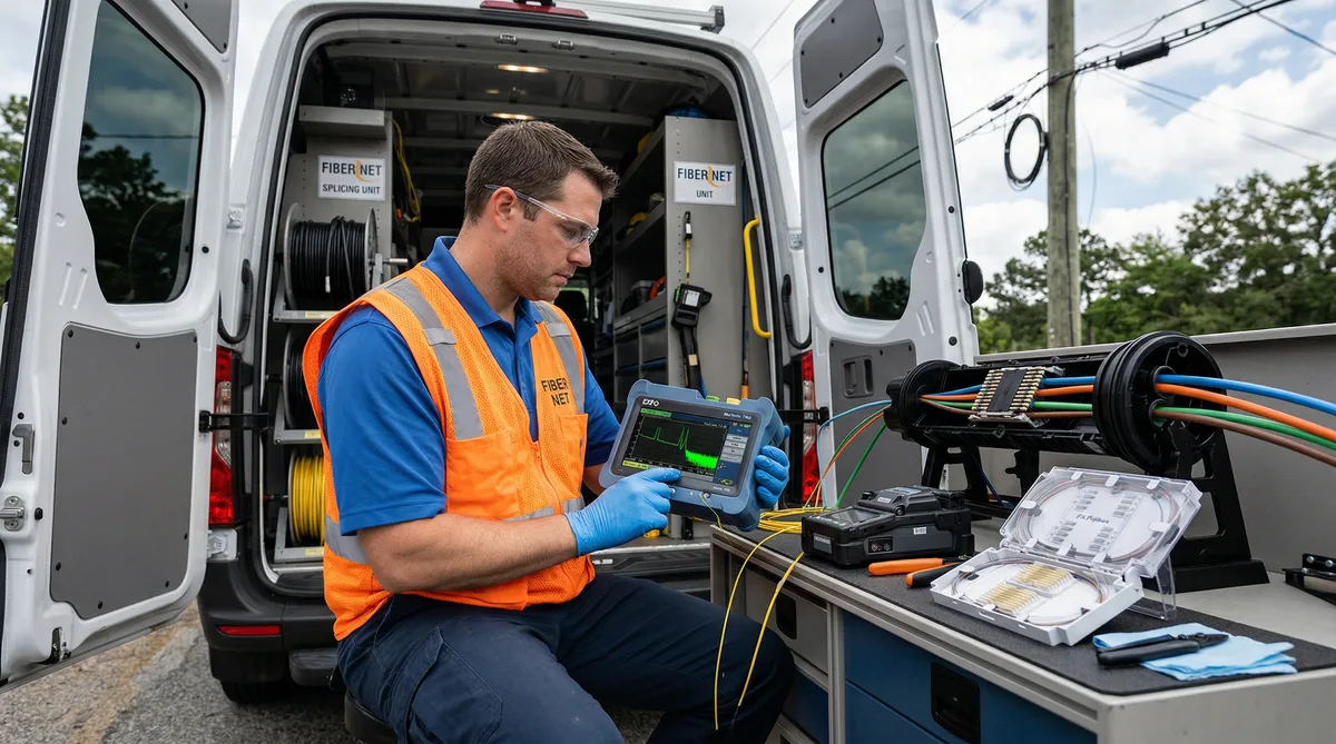
Reading an OTDR Trace: What the Events Actually Tell You
An OTDR trace is a graph of returned backscatter power versus distance. The horizontal axis is distance along the fiber. The vertical axis is optical power in dB — and it decreases as distance increases because fiber attenuates the signal. The slope of the line between events tells you the cable's dB/km attenuation. Events appear as deviations from that slope.
There are two types of events:
Reflective events appear as a spike — a sharp upward peak — followed by a step down. Connectors and mechanical splices produce reflective events because the air gap or index mismatch at the junction reflects some of the pulse back toward the OTDR. The height of the spike indicates the reflectance (optical return loss), and the step height indicates the insertion loss. On a well-terminated SC/APC connector, you want reflectance below −60 dB. SC/PC connectors typically come in around −40 to −55 dB. If you're seeing −30 dB reflectance on an SC/APC, someone contaminated or damaged that end face.
Non-reflective events are fusion splices. They appear as a step down (loss) or — confusingly — a step up (a gainer). No spike. Just a level change. The OTDR measures the loss by comparing the backscatter slope before and after the event.
To read the splice loss from a trace, you need the OTDR's loss analysis markers placed correctly on either side of the event — typically 10–20 meters back from the splice on each side to avoid the event dead zone. Most modern OTDRs (Viavi MTS-8000, EXFO FTB-720, JDSU T-BERD) do this automatically with their event analysis algorithms, but auto-analysis isn't always trustworthy on short spans or near the launch end. For acceptance purposes, verify that the markers are placed in the linear backscatter region, not in the event dead zone.
The Gainer Phenomenon: Why Your Trace Shows a Step Up at a Splice
Gainers confuse every field tech the first time they see one. The OTDR trace shows a positive step at a splice — like signal is being added rather than lost. That seems physically impossible. And it is physically impossible. The fiber isn't creating optical power. What's happening is a measurement artifact.
Here's the actual mechanism: OTDR measures loss by comparing the backscatter level before a splice to the backscatter level after the splice. Backscatter intensity depends on the fiber's backscatter coefficient, which is determined by the fiber's numerical aperture and core properties. Different fiber batches — or even different sections of the same manufacturer's cable — can have slightly different backscatter coefficients.
When the fiber on the far side of a splice has a higher backscatter coefficient than the fiber on the near side, the returning backscatter from the far side is stronger than expected. The OTDR interprets this as the signal being stronger after the splice than before it — a gainer. Typical gainers range from −0.02 to −0.15 dB. Larger apparent gains usually indicate a significant fiber geometry mismatch.
A gainer doesn't mean the splice is good. It means the measurement from this direction is not reliable. This is exactly why bidirectional OTDR testing is mandatory when individual splice losses must be documented. When you test from the other direction, the same splice shows an apparent loss. Average the two directional readings and you get the true splice loss.
The math: if Direction A shows −0.08 dB (a gainer) and Direction B shows +0.22 dB (a loss), the average is 0.07 dB. That's the actual splice loss you report. Both readings must be documented. Submitting only the Direction A result would hide a 0.22 dB splice — which might be marginal for a tight link budget — behind a spurious gainer reading.
Why Bidirectional OTDR Testing Is Not Optional
I've had contractors argue that bidirectional testing is overkill, that their fiber is all from the same spool, and that gainers won't be an issue. Maybe. But the specification doesn't say "unless you're confident." It says bidirectional testing is required when individual splice loss reporting is required. End of discussion.
Beyond the gainer problem, bidirectional testing catches asymmetric faults that single-direction testing misses. A microbend from a closure crimp may cause significant loss from one direction and only marginal loss from the other, depending on mode distribution. A contaminated splice tube may show up clearly in one direction and be masked by a nearby connector event in the other. Testing both directions and averaging isn't bureaucratic excess — it's the only way to get an accurate picture of what the splice is actually doing.
From a documentation standpoint, projects with formal acceptance criteria — including BEAD-funded deployments covered under your BEAD compliance checklist — will specifically require bidirectional traces. Submitting a single-direction trace package is grounds for rejection of the test documentation, which means a restest, which means construction schedule impact. Just do both directions from the start.
Acceptable Loss Values — A Reference Table
| Event Type | TIA-568.3-D Max | Typical Project Spec | Best Practice Target |
|---|---|---|---|
| Fusion splice (single-mode) | 0.3 dB per splice | 0.2 dB max / 0.1 dB avg | 0.05–0.08 dB avg |
| Connector insertion loss (SM) | 0.75 dB per mated pair | 0.5 dB per mated pair | 0.2–0.35 dB per mated pair |
| Connector reflectance (SC/APC) | −60 dB or better | −60 dB or better | −65 dB or better |
| Connector reflectance (SC/PC) | −40 dB or better | −45 dB or better | −50 dB or better |
| Mechanical splice | 0.75 dB per splice | Typically not permitted | Use fusion only for OSP |
| SM cable attenuation (G.652.D) | 0.4 dB/km at 1310 nm | 0.35 dB/km at 1310 nm | 0.33–0.35 dB/km typical |
| SM cable attenuation (G.652.D) | 0.4 dB/km at 1550 nm | 0.25 dB/km at 1550 nm | 0.19–0.22 dB/km typical |
These are the numbers you need in front of you when reviewing a test package. When a contractor submits results that show 0.02 dB at every splice, that should raise a question — not because the splices are necessarily bad, but because the OTDR instrument detection floor on most field units is around 0.03–0.05 dB. A consistent 0.02 dB reading often means the OTDR's resolution isn't fine enough to distinguish between a 0.01 and a 0.06 dB splice. It doesn't mean every splice is genuinely 0.02 dB. The instrument is reporting below its practical measurement floor. For acceptance purposes, what matters is that no splice is above the threshold and the link-level OLTS results pass the budget — not that every individual splice reads at some impossibly low value.
Common Disputes — And How to Resolve Them
A few patterns that come up on nearly every construction acceptance review:
"All our splices show 0.02 dB, so they all passed." See above. The instrument floor is the problem here. Ask for the OTDR instrument specs and confirm the minimum event detection threshold. If the instrument can't reliably resolve below 0.05 dB, a 0.02 dB reading is "indistinguishable from perfect" — not a measured value. This doesn't fail the splice, but it doesn't confirm it either. The OLTS end-to-end loss is what actually certifies the link.
Contractor submits single-direction traces only. Reject and request bidirectional traces. There's no argument here. If the spec requires bidirectional testing, single-direction results are incomplete. Schedule a retest.
A splice shows 0.32 dB in one direction, 0.08 dB in the other, average 0.20 dB. This is right at a typical project spec maximum. The QC engineer's call: does 0.20 dB average pass a "0.20 dB maximum" spec? Technically yes. But a 0.32 dB unidirectional reading warrants a closer look at the trace — is there a mechanical issue with the closure, or is the fiber geometry difference so significant that this splice might degrade over temperature cycling? At 0.20 dB average, I'd document it and flag it for periodic monitoring rather than requiring a resplice. At 0.25 dB average, I'd require the resplice.
Client asks why a splice shows as a "gain" but the contractor says everything passed. Explain the gainer phenomenon. If bidirectional testing was done and the average is below threshold, the splice passed. The gainer is an artifact, not a real gain. Document the bidirectional values and the average in the test report and move on.
Good as-built GIS documentation standards help resolve these disputes before they escalate, because the test records are properly attributed to specific fiber routes and splice locations from the start — not assembled retroactively from a pile of unorganized printouts.
When to Require a Resplice vs. Accept and Document
Resplicing costs money. The crew has to return to the closure, open it, re-strip and re-cleave the fiber, resplice, and retest. On a buried closure that requires excavation, that's a significant cost. The QC engineer doesn't get to be cavalier about requiring resplices — but also can't accept failures because the work is expensive to fix.
General guidance on when a resplice is required versus when you document and accept:
- Resplice required: Bidirectional average exceeds the project specification maximum per-splice threshold. No exceptions.
- Resplice required: Multiple splices in a single closure all running near the top of the threshold — even if each one individually passes, a cluster of 0.18–0.19 dB splices in one closure suggests a systematic problem (bad arc settings, contaminated V-groove, humidity in the splicer) that will likely produce more failures or degrade over time.
- Document and flag: A splice that passes the average threshold but shows significant directional asymmetry (e.g., −0.05 dB one way, +0.25 dB the other, average 0.10 dB). It passed. Flag it for monitoring.
- Document and accept: Everything within threshold, bidirectional testing completed, OLTS link-level loss passes the budget. That's a passing test package. Sign it off and move to the next closure.
The field data accuracy principles that apply to survey work apply here too: the decision should be based on what the data actually shows, not on pressure from the contractor to clear the closeout milestone. Document your reasoning when you accept a marginal result. If that splice degrades in three years, you want a record showing it was within spec at acceptance.
BEAD Documentation Requirements for OTDR Testing
BEAD-funded projects add a documentation layer on top of the standard TIA requirements. The specific requirements vary by state, but common elements include:
- Bidirectional OTDR traces for every fiber in the plant, stored as both PDF and native instrument files (.sor format)
- OLTS end-to-end insertion loss for every fiber, documented at both 1310 nm and 1550 nm
- Splice loss summary tables correlating each splice event to its GIS location (typically referenced to the as-built structure ID)
- Instrument calibration records for all test equipment used
- Technician qualification documentation in some state programs
The .sor file requirement matters. PDF traces are human-readable but can't be re-analyzed if a question arises later. The .sor format (Bellcore standard, supported by virtually all OTDR vendors) preserves the raw trace data so the file can be opened in analysis software and re-evaluated with different markers or settings. If a dispute arises six months post-acceptance, the .sor file is how you resolve it. Insisting on .sor file submission upfront saves everyone headaches later.
For a complete picture of what BEAD subgrantee documentation requires beyond testing records, the BEAD compliance checklist and the broader construction package deliverables framework are worth reviewing together — the testing package is one deliverable in a larger closeout documentation set.
Frequently Asked Questions
What is an acceptable splice loss for fiber optic cable?
TIA-568.3-D sets the maximum per-splice loss at 0.3 dB for field-installed fusion splices. Most ISP and municipal project specifications require a tighter threshold — typically 0.1 dB average with a 0.2 dB maximum per splice. For BEAD-funded projects, check your state's specific acceptance criteria, which may differ from the TIA baseline.
Why is bidirectional OTDR testing required?
Bidirectional testing is required because backscatter coefficient differences between fiber segments can make a splice appear as a gain in one direction and a loss in the other. Neither reading alone is accurate. The true splice loss is the average of the two directional measurements. Accepting a single-direction OTDR trace as the splice loss value can result in accepting bad splices that appear acceptable from one end.
What is the difference between Tier 1 and Tier 2 fiber testing?
Tier 1 testing per TIA-568.3-D uses an Optical Loss Test Set (OLTS) — a light source and power meter — to measure insertion loss from end to end. This is the certification test required for every fiber in a link. Tier 2 testing uses an OTDR to characterize the link: identifying event locations, measuring individual splice and connector losses, and detecting reflections. Tier 2 provides the diagnostic picture; Tier 1 provides the pass/fail certification number.
What causes a "gainer" on an OTDR trace?
A gainer is an apparent increase in optical power at a splice event — the OTDR trace shows a step upward instead of a step down. It's caused by a difference in backscatter coefficients between the two fibers being joined. If the fiber on the far side of the splice has a higher backscatter coefficient, the returning signal appears stronger and the OTDR calculates a negative loss. The splice isn't actually adding power — it's a measurement artifact. The true loss is found by averaging bidirectional measurements.
Can OTDR testing alone certify a fiber link?
No. OTDR testing (Tier 2) cannot certify a fiber link by itself. TIA-568.3-D requires Tier 1 OLTS testing — using a calibrated light source and optical power meter — to measure actual end-to-end insertion loss for certification. OTDR is a diagnostic tool that identifies where problems are located and characterizes individual events, but it doesn't measure absolute loss with sufficient accuracy for link certification. Both tests are typically required on projects with formal acceptance criteria.
Getting Test Documentation Right From the Start
Test documentation disputes are almost always avoidable. They happen when the acceptance criteria aren't specified clearly before construction starts, when the testing protocol isn't agreed to in writing, or when whoever is reviewing the results doesn't understand what they're looking at. None of those are good reasons to end up in a resplice argument at the end of a three-month build.
The QC engineer reviewing OTDR traces needs to understand the gainer phenomenon, bidirectional averaging, the difference between Tier 1 and Tier 2, and the specific project thresholds — not just the TIA baseline. The contractor needs to know exactly what format the documentation must take, including whether .sor files are required and how splice events need to be cross-referenced to as-built records.
Our team at Draftech has reviewed test packages on projects across 22 states, from small cooperative FTTH builds to large BEAD-funded multi-county deployments. If you need a second opinion on an OTDR package, have a dispute you're trying to resolve with a contractor, or want your testing protocol reviewed before construction starts, reach out at info@draftech.com. Our as-built documentation services include QC review of test records as part of the closeout package.