- What GIS-Native Design Actually Means — and What It Doesn't
- Route Optimization: Where the Big Savings Live
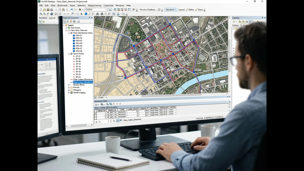
- Automated BOQ Generation and Why Manual Counts Are Costing You
- Clash Detection Before the Bore Crew Hits the Ground
- As-Built Documentation: The Part That Usually Gets Compromised
- The AutoCAD Role in a GIS-First Workflow
GIS-driven fiber network planning isn't a new concept. But the gap between engineering firms that have fully integrated GIS into their design workflow — from initial route planning through as-built documentation — and those still exporting AutoCAD files at the end of a project has never been wider. Or more expensive for the builders who don't ask which category their engineering partner falls into.
The 30% figure isn't marketing. It's what we consistently see when we compare the total project cost — engineering, permitting, construction, and change orders — on equivalent deployments designed with AutoCAD-primary workflows versus GIS-native workflows. The savings don't come from one place. They accumulate across route optimization, materials quantification, clash detection, permit efficiency, and construction change order reduction. Each of those is worth examining individually, because the mechanism matters as much as the outcome.
What GIS-Native Fiber Network Planning Actually Means for Cost Reduction
GIS-native fiber network planning uses a georeferenced spatial database as the authoritative design source — enabling route optimization, automated BOQ generation, clash detection, and as-built updating from a single data model. Studies and project-level data consistently show GIS-driven design reduces fiber construction cost 15–25% versus CAD-only workflows by optimizing routes before construction begins and eliminating manual quantity counting errors.
Being "GIS-native" doesn't mean drawing fiber routes in ArcGIS instead of AutoCAD. It means that the spatial data model is the authoritative source from the first moment of design — that every cable segment, every conduit, every splice enclosure, every equipment location exists as a georeferenced feature in a spatial database with attributes attached, not as a line on a drawing that someone will later try to convert into a GIS layer.
AutoCAD has been the backbone of OSP design for thirty years, and it's still excellent at what it does: producing precise, print-ready construction drawings. The problem isn't AutoCAD. The problem is the workflow where engineers design in AutoCAD, produce construction drawings, and then someone tries to extract a GIS dataset from those drawings after the fact. The translation loses attribute data. It introduces geometric errors. It requires manual QA that takes days and still produces an inferior dataset compared to what you'd have gotten from a native GIS workflow.
Platforms like 3GIS — which is built specifically for telecom OSP design — and ArcGIS with OSP-specific extensions allow engineers to work directly in a spatial database environment where the design data is simultaneously a spatial record and an engineering drawing source. Design changes propagate through the dataset. Materials quantities update automatically. The same data that drives the construction drawing drives the permit application and the as-built submission.
GIS Route Optimization for Fiber Networks: Where the Big Cost Savings Live
GIS route optimization for fiber network planning identifies shorter, cheaper, or easier-to-permit construction paths by spatially analyzing existing conduit, aerial plant, parcel boundaries, terrain, and permit complexity — analysis AutoCAD cannot perform. Typical route optimization exercises reduce planned fiber route miles 8–18% before construction begins, translating directly to lower construction cost per home passed.
The single largest cost reduction from GIS-driven planning comes from route optimization — identifying the physically shorter, cheaper, or easier-to-permit construction path that AutoCAD drawing in isolation wouldn't reveal. GIS provides the spatial analysis tools to find those paths. AutoCAD doesn't.
Here's a concrete example. On a 2,400-location rural FTTH deployment in the upper Midwest, our initial route planning identified what appeared to be the logical feeder path along a county road — 14.2 miles from the hub site to the edge of the service area. When we ran a spatial analysis overlaying the cadastral parcel data, existing utility easements, and the fiber locations of a cooperative's existing plant, we found a 9.8-mile alternative route that followed existing utility easements, avoided two county road crossings, and reduced the make-ready scope from 280 poles to 160. The engineering data was all in GIS. The route comparison was a spatial analysis operation. In AutoCAD, you'd need to redraw both routes, manually calculate the cost difference, and do the comparison on paper. In GIS, it's a morning's work.
Over a deployment with 80,000 feet of new conduit at $35–$55 per foot for direct bore, a 10–15% route length reduction from spatial optimization is $280,000–$660,000 in construction savings. That's before you count the reduced make-ready scope, the reduced permit count, and the shorter construction schedule.
Automated BOQ Generation and Why Manual Counts Are Costing You
A Bill of Quantities generated from a GIS spatial database is fundamentally different from one compiled manually from AutoCAD drawings. In a properly attributed GIS model, every cable segment has a known length (calculated from actual route geometry, not a scaled-off drawing), a cable type, and a splice count. Every conduit segment has a diameter, a fill ratio, and a construction method. Every enclosure has a type and a port count. The BOQ is a database query — a sum of attributes across all features in the design dataset.
Manual BOQs, compiled by engineers measuring AutoCAD drawings, have error rates we've measured at 8–15% on large projects. That sounds small until you multiply it across a $15M material procurement. A 10% error in fiber cable quantity on a 500,000-foot project at $0.45 per foot is $22,500 in over-procurement — or, worse, a mid-project shortage that delays construction while emergency procurement is arranged. We've seen both. Neither is fun to explain to a client.
In 3GIS and ArcGIS-based OSP workflows, the BOQ is auto-generated and updates every time a design change is made. A route extension adds 2,200 feet of cable to the BOQ automatically. A splice point relocation recalculates the cable lengths of both affected segments. The BOQ is always current. The procurement team is always working from accurate numbers.
Clash Detection Before the Bore Crew Hits the Ground
Underground fiber construction lives and dies by what's already in the ground. Gas lines, water mains, power conduits, storm drains, existing telecom infrastructure — these exist at specific locations in the subsurface, and any bore path that intersects them is either a construction delay or a safety incident. GIS-based clash detection is the engineering step that identifies those conflicts before the drill bit does.
This requires good utility data, which isn't always easy to get. 811 records vary dramatically in quality and currency by region. Municipal GIS layers for water and sewer are often years out of date. But even imperfect utility data in GIS allows conflict analysis that identifies the most likely problem zones — the intersections where a gas main and your proposed bore path share the same 10-foot-wide corridor, the locations where an existing telecom duct bank probably occupies the same easement your design is counting on.
When we run clash analysis on a new design and find 40 potential conflicts in a 15-mile route, that's 40 places where a field crew doing a vacuum excavation test hole saves potentially thousands of dollars in construction rework. Not all 40 will be actual conflicts — utility data is imperfect — but the 6 or 8 that are real conflicts are worth far more than the cost of the analysis.
As-Built Documentation: The Part That Usually Gets Compromised
In a GIS-native design workflow, as-built documentation isn't a separate post-construction deliverable. It's an update to the design database — field crews with Trimble GPS units, Juniper Systems collectors, or mobile GIS apps recording the actual installed locations of conduit, cables, and enclosures directly into the GIS system. The as-built is the design GIS dataset with verified, field-corrected locations replacing the design locations.
Compare that to the AutoCAD-based alternative, where field crews mark up paper drawings, those markups are scanned, and a CAD technician manually updates the drawing — possibly weeks after the fact. The resulting as-built has location errors that come from field measurement imprecision, markup misinterpretation, and transcription mistakes. The data also still needs to be converted to GIS for any downstream network management or regulatory reporting.
For BEAD projects specifically, where as-built GIS data is a compliance requirement, the difference between a project managed in native GIS from day one and one that requires post-construction conversion is typically 6–8 weeks of additional work and a substantially lower-quality final dataset. We've been asked to help rescue as-built packages from projects designed in AutoCAD. It's expensive and time-consuming work that didn't need to happen.
The AutoCAD Role in a GIS-First Fiber Network Planning Workflow
AutoCAD doesn't disappear from a GIS-native workflow. It remains the best tool for producing construction drawings — the plan-and-profile sheets, the detailed splice diagrams, the conduit section details that field crews read on the job site. The difference is that in a GIS-first workflow, AutoCAD drawings are generated from the GIS data model, not the other way around. Changes made in GIS propagate to the AutoCAD output. The GIS model is always the master.
This combination — GIS as the spatial intelligence layer, AutoCAD as the drawing production tool — is what we run at Draftech on all medium and large-scale deployments. It requires investment in integration between the two environments, and it requires engineers fluent in both platforms. But the deliverable quality, the construction cost outcomes, and the schedule efficiency justify it on every project above about 500 passings.
If you're evaluating engineering partners for a fiber deployment and wondering whether their workflow is going to affect your construction costs, the questions to ask are simple: what platform are your designs native in, how is the BOQ generated, and what format is your as-built delivered in? The answers tell you everything about the cost risk you're taking on. Our team is happy to walk through our GIS workflow and how it applies to your specific project — reach out at info@draftech.com.